Directional support structure

a directional support and support technology, applied in the direction of machine supports, heat collector mountings/supports, light and heating apparatus, etc., can solve the problems of inability to precisely hold large directional objects yet allow for ease of adjustment, what is lacking in the art, etc., to prevent further rotational movement, precise adjustment, and eliminate disengagement of directional devices

Inactive Publication Date: 2007-07-05
STANEY WAYNE
View PDF30 Cites 9 Cited by
  • Summary
  • Abstract
  • Description
  • Claims
  • Application Information

AI Technical Summary

Benefits of technology

[0006] Set forth is a directional support structure for use with solar panels, flat or raised satellite antennas, and the like structures required to be directionally facing a fixed point in space. The directional support structure includes an adjustable bracket that allows for pivoting of the mounting plate even when the mounting plate is loaded with solar panels or satellite panels, despite the weight of such devices. Rotational or azimuth movement is maintained by use of a mounting bracket secured to a base member that allows rotation with operator safety in mind by eliminating disengagement of the directional devic

Problems solved by technology

The weight of the panels is dependant upon the panel size but can be quite heavy if the solar panel includes circulating water.
One of the problems with the prior art support structures is the inability to precisely hold large directional objects yet allow for ease of adjustment.
In addition, prior art devices have not disclosed the necessity for a support structure c

Method used


Image

  • Directional support structure
  • Directional support structure
  • Directional support structure

Examples


Embodiment Construction

, Drawings, and the Claims appended herewith.

BRIEF DESCRIPTION OF THE DRAWINGS

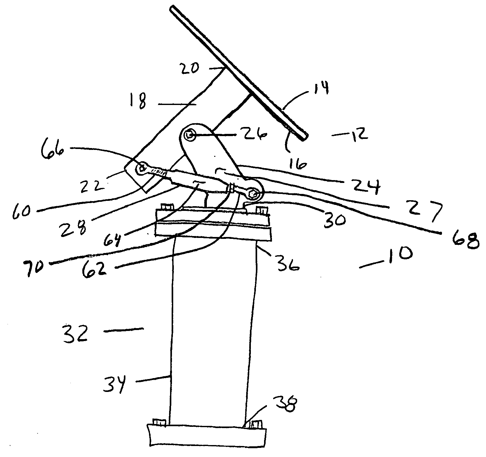
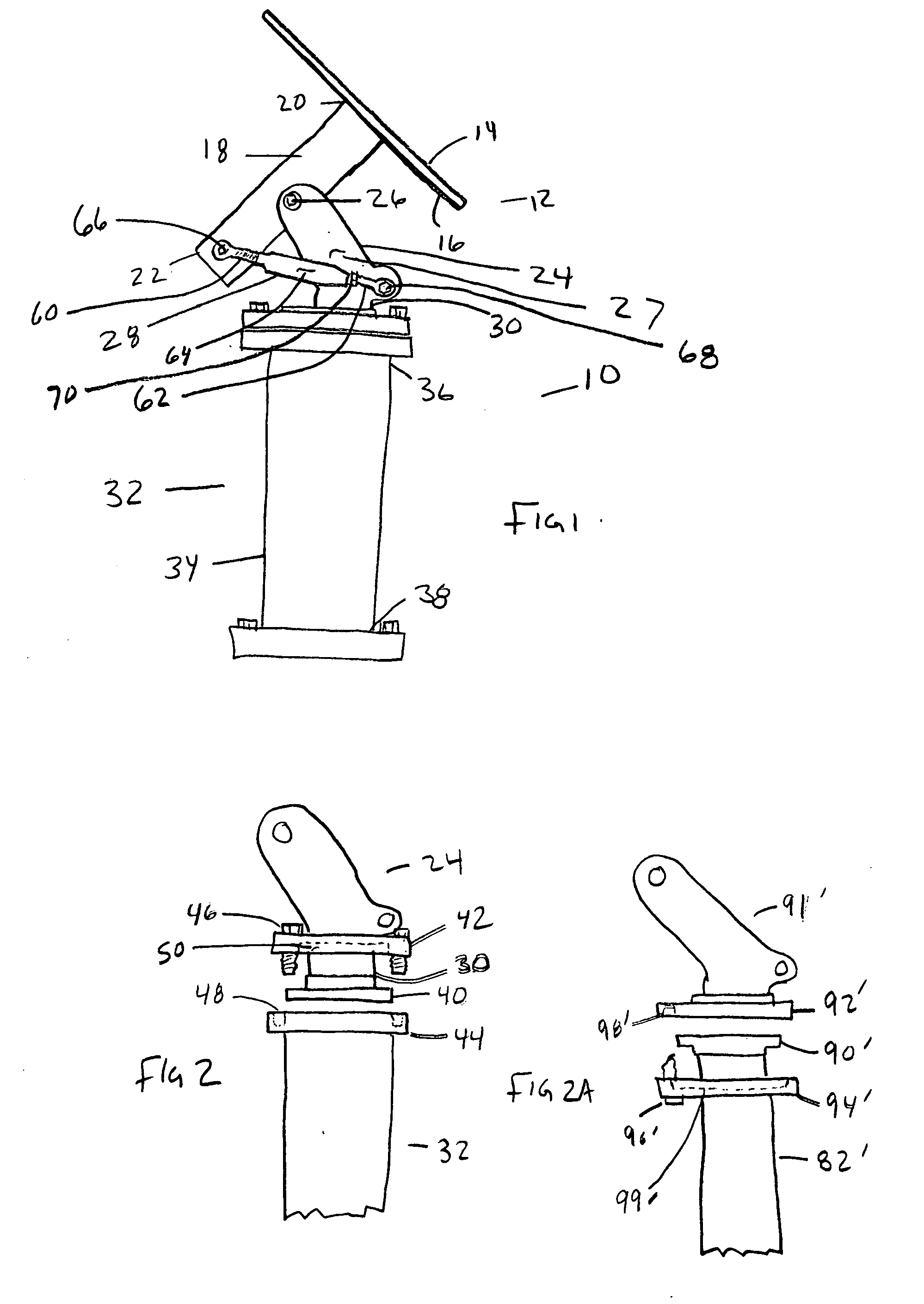
[0014]FIG. 1 is a side plane view of the Directional Support Structure;

[0015]FIG. 1a is a pictorial of FIG. 1;

[0016]FIG. 2 is an exploded view illustrating a flaring attached to a lower end of the mounting bracket;

[0017]FIG. 2a is an exploded view illustrating a flaring attached to the upper end of the base member;

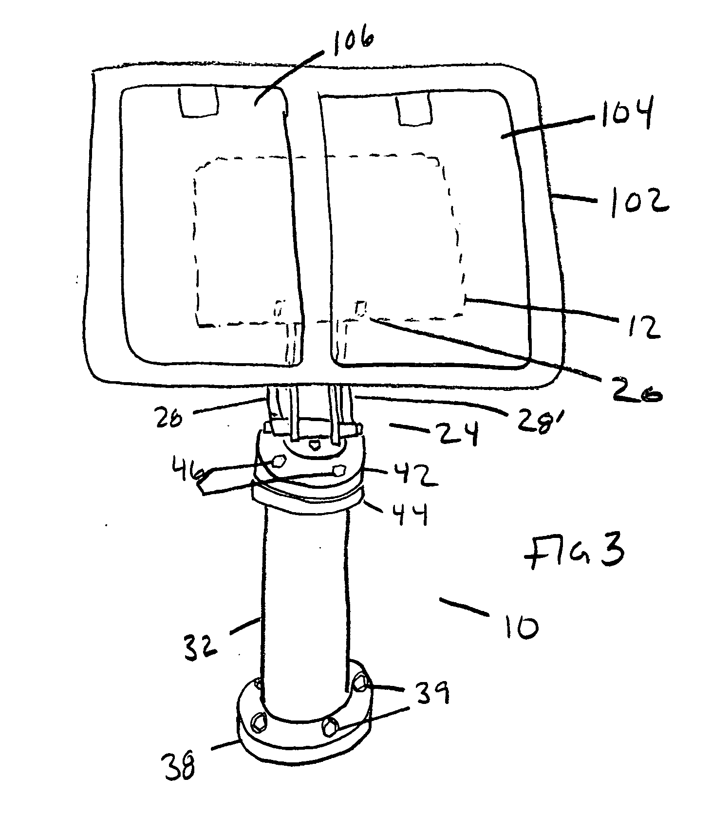
[0018]FIG. 3 illustrates a front perspective view of the Directional Support Structure within an attached basin for receipt of solar panels;

[0019]FIG. 3a is a pictorial of FIG. 3;

[0020]FIG. 4 is a side perspective of the Directional Support Structure with solar panels placed in a basin;

[0021]FIG. 4a is a pictorial of FIG. 4; and

[0022]FIG. 5 is a side perspective view of the Directional Support Structure with a satellite antenna and collector.

DESCRIPTION OF THE PREFERRED EMBODIMENTS

[0023] As required, detailed embodiments of the present invention are disclosed herein; however, it is to ...


PUM


Abstract

A directional support structure for use with solar panels, flat satellite antennas, and the like items that are directed toward a point in space. The support structure has a mounting plate with an extension tube extending outwardly therefrom and is pivotally secured to a mounting bracket permitting latitude alignment of the mounting plate. At least one adjustable turnbuckle is attached to the extension tube and the mounting bracket to provide adjustable alignment of the mounting plate, the turnbuckle can then be locked into position. The mounting bracket is further secured to a base member permitting rotational or azimuth positioning of the mounting plate. The base member includes an attached first flange positioned along an upper end of the base member, an attached flaring positioned to the lower end of the mounting bracket, and an unattached second flange positioned over the flaring and securable to the first flange with fasteners. The support structure can be loosely assembled with industrial solar panels or antennas yet is effortless to position for optimum directional positioning. The mounting bracket may then be rotationally positioned and the flanges fastened together to lock the mounting bracket in a fixed position.

Description

FIELD OF THE INVENTION [0001] The present invention relates to field of support structures and, more particularly, to a support structure for solar panel collectors, satellite antennas and other objects that need to be fixed toward a point in space. BACKGROUND INFORMATION [0002] Solar panels and satellite antennas are directed to a particular point in space to be effective. A solar panel collector must either be directed toward the sun where it will be most effective or made to track the sun as it moves across the sky. Solar panels are used to collect energy from the Sun and require optimum positioning whether the energy is for heating of water or providing electrical power. The weight of the panels is dependant upon the panel size but can be quite heavy if the solar panel includes circulating water. [0003] Satellite antennas, both flat and parabolic, can be found throughout the world for communication purposes. These antennas must also be directed to a particular point in space to ...

Claims


Application Information

Patent Timeline
IPC IPC(8): A47G29/00
CPCF16M11/10F16M11/12F16M11/2014F24J2/523F24J2/541F24J2002/5465Y10T16/53835Y02E10/47Y10T403/645Y10T403/642Y10T403/64Y10T16/5383Y10T403/4688H01Q1/1264F24S2030/135F24S30/425F24S25/10F16B2200/50F16B2200/406F16B2200/503F16B2200/506
Inventor STANEY, WAYNE
Owner STANEY WAYNE
Why Eureka
Try Eureka