Pistol with loaded chamber indicator

a technology of loaded chamber and indicator, which is applied in the field of pistols, can solve the problems of not readily noticeable indicators, difficult for pistol users to visually distinguish loaded chamber conditions from empty chamber conditions by using such devices, and may not be practical or possible to open the chamber and observe the loaded condition of the same. the effect of noticeabl

Inactive Publication Date: 2008-06-10
STURM RUGER & CO INC
View PDF20 Cites 8 Cited by
  • Summary
  • Abstract
  • Description
  • Claims
  • Application Information

AI Technical Summary

Benefits of technology

[0007]A preferred embodiment provides a moveable loaded chamber indicator for a pistol that advantageously does not require cutting away of the rear barrel or chamber, thereby providing substantial structural support of the cartridge casing when the cartridge is loaded in the barrel or chamber. The preferred embodiment further advantageously provides a loaded chamber indicator that is more readily noticeable to a pistol user from a visual and tactile standpoint than known indicators.
[0008]In a preferred embodiment, the loaded chamber indicator operates by contact with the cartridge rim which remains outside of, and to the rear of or behind the chamber when the cartridge is loaded therein. Accordingly, the structural integrity of the chamber is not compromised by any openings cut through the chamber walls into the chamber like the known indicators discussed above. Therefore, the relatively fragile rimfire cartridge casing may be substantially and properly supported by the chamber.
[0009]In a rimfire cartridge, striking the cartridge rim from the lateral or side direction (instead of from the normal rear firing direction as with a firing pin) does not ignite the primer because the “squeezing” deformation of the rim needed to ignite the primer material (discussed above) is not created by impacting the rim from the side. In addition, the arched shape of the rim presented in the lateral direction makes the rim inherently stronger and more resistant to deformation from a blow to the side. Accordingly, the side of the cartridge rim which may conveniently be used to activate the indicator.
[0017]Broadly speaking, the foregoing rigid loaded chamber indicating element and energy-absorbing indicating elements described above all provide a surface which functions to contact the rim of a cartridge loaded in the chamber and which surface is movable from a first position to a second position. At least part of the respective indicating element protrudes from the exterior of the pistol in the second position to visually and tactilely communicate a loaded chamber condition to a pistol user. The energy-absorbing loaded chamber indicating elements further provide structures which function to be at least partially flexible and movable in response to a lateral impact or force imparted to the side of the indicating element so as to absorb at least some of the impact energy.

Problems solved by technology

While the loaded condition of a firearm's chamber is customarily and most positively checked by the user opening the action and visually observing the presence of a cartridge therein, there have been prior devices which attempt to augment this procedure by providing a mechanical device to signal the chamber's state of readiness, particularly in military firearms where opening the chamber and observing the loaded condition of same may not be practical or possible due to the need for stealth.
Moreover, the clip does not protrude beyond the exterior surface of the pistol in a loaded chamber condition, making the indicator not readily noticeable.
Both of these factors make it difficult for a pistol user to visually distinguish a loaded chamber condition from an empty chamber condition by use of such devices.
Dirt, unburned gun powder residue, carbon build-up, and grease may obscure the small viewing ports and render them ineffective.
A drawback of the foregoing known loaded chamber indicators is that they are also not suitable for use with all types of known self-contained cartridges currently on the market today because the window cutouts in the rear barrel or chamber reduce structural support of the cartridge casing and rim.
In particular, the foregoing indicators are not well-suited for the very popular rimfire-type cartridges, such as the .22 Long Rifle, which optimally require substantial structural support of the cartridge casing and rim during firing.
There has never been a loaded chamber indicator in the prior art that functions in a truly satisfactory fashion on firearms chambered for rimfire-type ammunition, which comprise a large percentage of the firearms sold.

Method used


Image

  • Pistol with loaded chamber indicator
  • Pistol with loaded chamber indicator
  • Pistol with loaded chamber indicator

Examples


Embodiment Construction

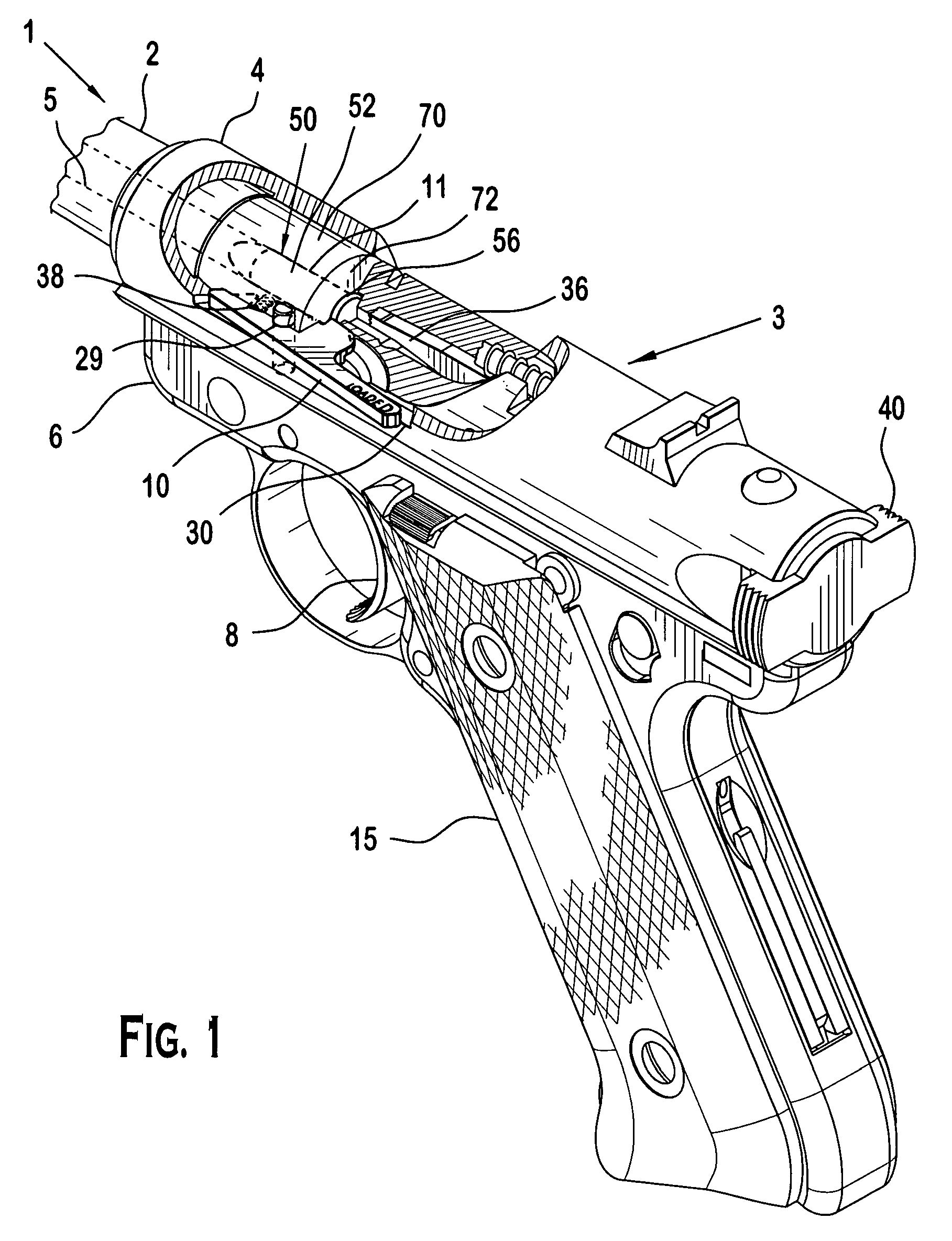
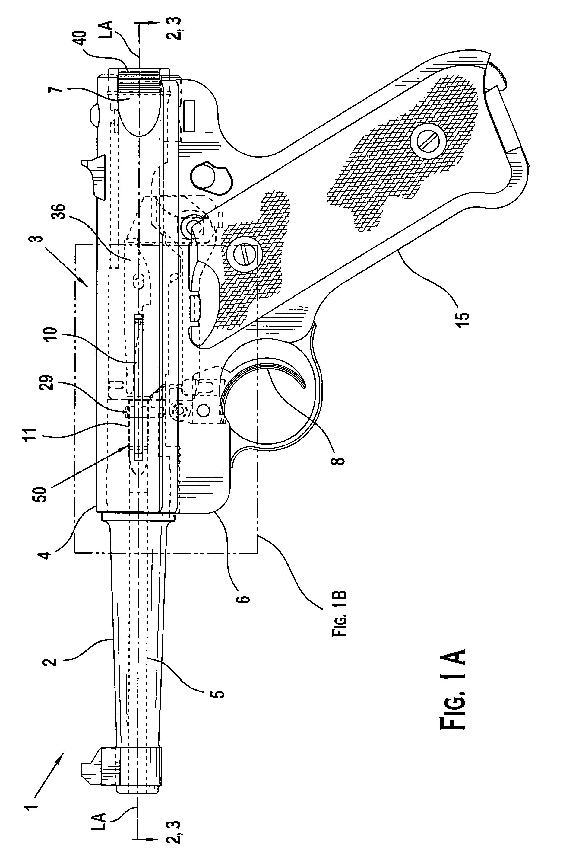
[0063]Referring generally to FIGS. 1-3, a preferred embodiment will now be described for convenience with reference to a rimfire-type pistol in the form of an autoloading pistol. It will be appreciated that the preferred embodiment is equally applicable for use with other type pistols including, without limitation, non-autoloading pistols, centerfire-type cartridge firing pistols, etc. In addition, the preferred embodiment may be used in non-firearm applications where a tactile and visual indication of a component operating position is desired.

[0064]Pistol 1 includes a longitudinally-extending barrel 2 with longitudinal bore 5 therethrough and a generally hollow-structured receiver 4 in operational relationship with barrel 2. In a preferred embodiment, receiver 4 is disposed adjacent to and preferably attached to barrel 2; the combination defining a barrel-receiver assembly 3. Receiver 4 has an exterior surface 80 and an interior surface 82 defining a cavity 86 therein (see, e.g., F...


PUM


Abstract

A pistol including a loaded chamber indicator to identify the presence of a cartridge loaded in the firing chamber. The pistol may generally include a barrel, a receiver attached to the barrel thereby defining a barrel-receiver assembly, and a chamber associated with the barrel-receiver assembly. An indicating element is provided which in one embodiment may be pivotally mounted in the barrel-receiver assembly. The indicating element is displaceable in response to contact by the cartridge from a first position which may in one embodiment correspond to an absence of a cartridge loaded in the chamber, to a second position which may in one embodiment correspond to a presence of a cartridge loaded in the chamber. A biasing member, such as a spring, may be provided to bias the indicating element towards the first position. In one embodiment, the indicating element protrudes outwards from the exterior of the pistol in response to contact by the cartridge rim to provide a visual and tactile indication of a loaded chamber condition to a user of the pistol.

Description

CROSS-REFERENCE TO RELATED APPLICATIONS[0001]This application is a continuation-in-part of prior U.S. patent application Ser. No. 10 / 825,509 filed Apr. 15, 2004 now abandoned, which is incorporated herein by reference.BACKGROUND OF THE INVENTION[0002]The present invention generally relates to firearms, and more particularly to an improved device suitable for use with, but not limited to rimfire-type cartridges to indicate the presence of a cartridge in the chamber of a pistol (i.e., a “loaded chamber”).[0003]While the loaded condition of a firearm's chamber is customarily and most positively checked by the user opening the action and visually observing the presence of a cartridge therein, there have been prior devices which attempt to augment this procedure by providing a mechanical device to signal the chamber's state of readiness, particularly in military firearms where opening the chamber and observing the loaded condition of same may not be practical or possible due to the need ...

Claims


Application Information

Patent Timeline
Patent Type & Authority Patents(United States)
IPC IPC(8): F41A9/53
CPCF41A9/53
Inventor MCGARRY, JAMES
Owner STURM RUGER & CO INC
Why Eureka
Try Eureka