Central vacuum cleaning system control subsystems

a technology of control subsystem and vacuum cleaner, which is applied in vacuum cleaner equipment, lighting and heating equipment, coupling device connections, etc., can solve the problem that the installation of low-voltage wires can involve a great deal of effor

Inactive Publication Date: 2008-07-22
CUBE INVESTMENTS
View PDF98 Cites 56 Cited by
  • Summary
  • Abstract
  • Description
  • Claims
  • Application Information

AI Technical Summary

Problems solved by technology

Installation of the low voltage wires can involve a great deal of effort, particularly when the system is being installed in an existing building.

Method used


Image

  • Central vacuum cleaning system control subsystems
  • Central vacuum cleaning system control subsystems
  • Central vacuum cleaning system control subsystems

Examples


Embodiment Construction

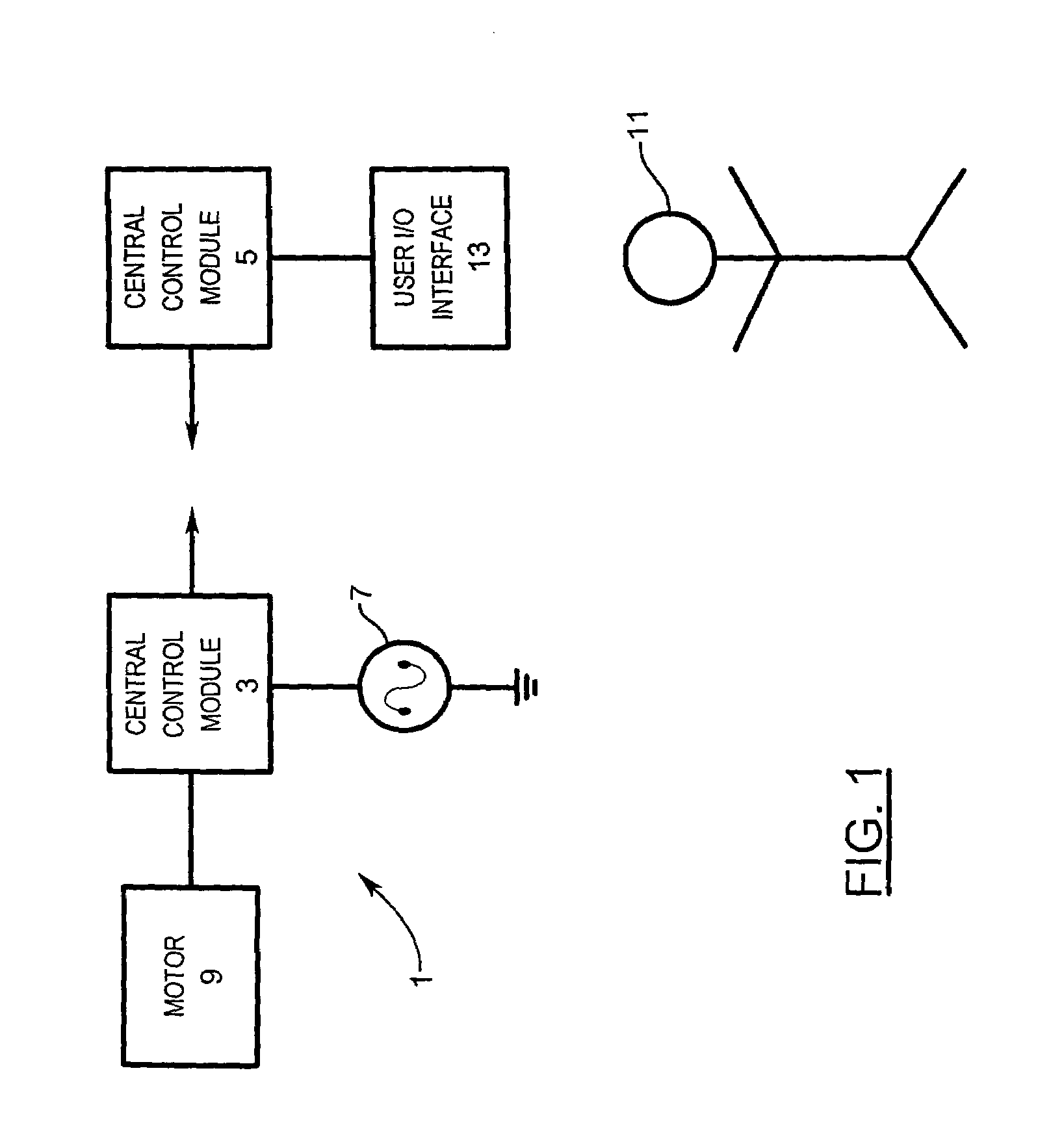
[0040]Referring to FIG. 1, a central vacuum cleaning system control subsystem 1 has a central control module 3 and a remote control module 5.

[0041]The central control module 3 controls power from a power source 7 to a motor 9, and by doing so the central control module 3 controls the operation of the motor 9. The power source 7 is typically line voltage, for example, 120V or 240V, 60 Hz AC in North America or 230V, 50 Hz AC in Europe.

[0042]The remote control module 5 is connected to a user input / output interface 13. The remote control module 5 receives input from a user 11 through the interface 13. User input may be as simple as a request for a change of state of the motor 9 where the interface 13 would be a toggle switch 13.

[0043]The remote control module 5 is a wireless transmitter. It encodes the input received from the user for wireless transmission to the central control module 3 as indicated by the arcs 15. The central control module 3 is a wireless receiver. It receives the w...


PUM


Abstract

A central vacuum cleaning system control subsystem for use in a central vacuum cleaning system having a motor includes a central vacuum unit control module with a receiver for wirelessly receiving command signals, and a power stage for controlling the motor in accordance with command signals received through the receiver. The control module is stable in high ambient temperature. Current flowing to the motor is sensed, and motor overcurrent and undercurrent conditions are determined. The control module determines when the motor is in an overcurrent condition. Power stage has a triac for controlling power to the motor. The control module also has a microprocessor that compares the current sensed against a normal operating current to determine overcurrent condition. Power to motor ceases when overcurrent condition exists. A generator is powered by air flow in a cleaning system for production of electrical energy.

Description

CROSS-REFERENCE TO RELATED APPLICATIONS[0001]This application is a continuation-in-part of co-pending U.S. patent application Ser. No. 10 / 843,321 filed 12 May 2004 under title Central Vacuum Cleaning System Motor Control Mounting Post, Mounting Configuration, and Mounting Methods, and claims priority from, and the benefit of, the filing date of the above application. The contents of the above application is hereby incorporated by reference into the Detailed Description hereof.FIELD OF THE INVENTION[0002]The invention relates to central vacuum cleaning systems. More particularly, it relates to control subsystems for central vacuum cleaning systems.BACKGROUND OF THE INVENTION[0003]Many modern buildings have central vacuum cleaning systems. These systems have a suction motor to create a vacuum in a series of pipes through the building. A user of the system connects a flexible hose to one of the pipes. The hose has a handle for the user to grasp. The handle is further connected to one o...

Claims


Application Information

Patent Timeline
Patent Type & Authority Patents(United States)
IPC IPC(8): H02H7/00A47L5/38A47L9/28H01R13/66H01R13/717H02H7/08
CPCA47L5/38A47L9/2842A47L9/2857A47L9/2889A47L9/2894H01R13/6658H01R13/7172H01R13/7175A47L9/2805A47L9/2831A47L9/2884H01R13/717H02H7/0833Y02B40/82Y02B40/00
Inventor CUNNINGHAM, J. VERN
Owner CUBE INVESTMENTS
Why Eureka
Try Eureka