Router, terminal apparatus, communication system and routing method

a terminal and routing technology, applied in the field of routing methods, can solve the problems of waste of network resources along the route, and achieve the effect of large delay time and effective utilization of network resources

Inactive Publication Date: 2008-08-05
NTT DOCOMO INC
View PDF17 Cites 6 Cited by
  • Summary
  • Abstract
  • Description
  • Claims
  • Application Information

AI Technical Summary

Benefits of technology

[0011]An object of the present invention is to effectively utilize network resources by eliminating the transfer processing of a data packet with a large delay time and which is unnecessary for the reception terminal.

Problems solved by technology

In other words, even in a case where a delay in the transfer of the data packet in the network occurs, and the data packet no longer satisfies the application quality since it has not been able to reach the reception terminal within the acceptable delay time, the router 202 will still transfer that data packet to the reception terminal.
If the reception terminal receives that kind of data packet, it will simply discard the data packet since it cannot be normally recreated as an application.
Furthermore, there are cases where network resources along the route are wasted due to the router 202 performing such unnecessary transfer processing.

Method used


Image

  • Router, terminal apparatus, communication system and routing method
  • Router, terminal apparatus, communication system and routing method
  • Router, terminal apparatus, communication system and routing method

Examples


Embodiment Construction

[0026]An embodiment of the present invention will be described with reference to the accompanying drawings.

Communication System

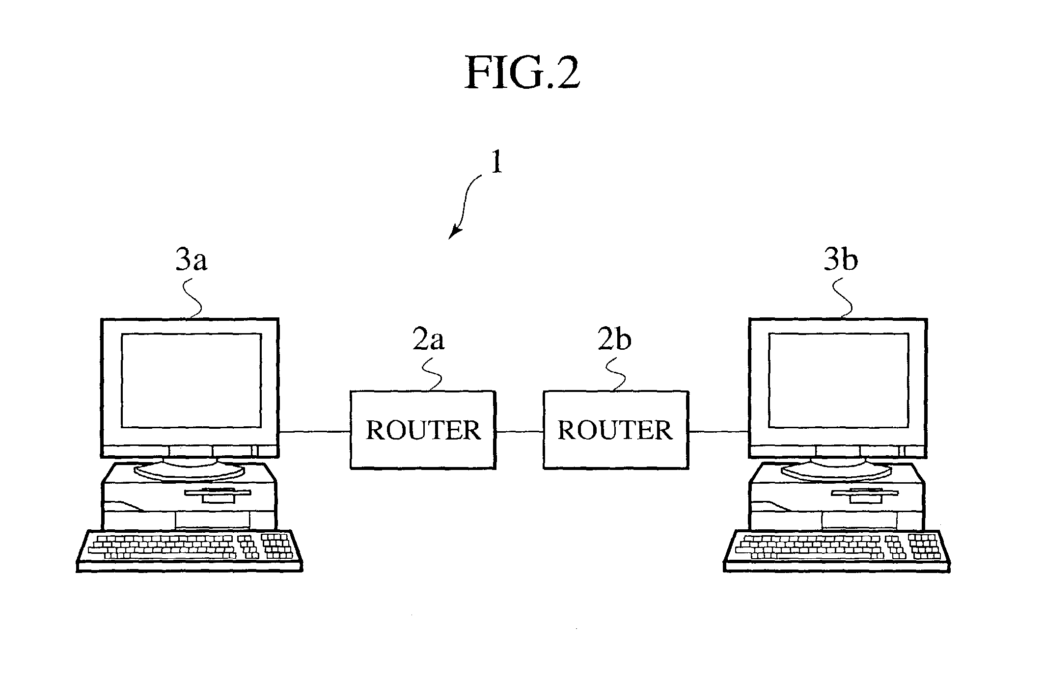
[0027]As shown in FIG. 2, a communication system 1 includes a plurality of routers 2a and 2b, a transmission terminal 3a, and a reception terminal 3b. When the transmission terminal 3a transmits a packet, the routers 2a and 2b transfers the packet so as to deliver it to the reception terminal 3b. The reception terminal 3b then receives the packet.

(Router)

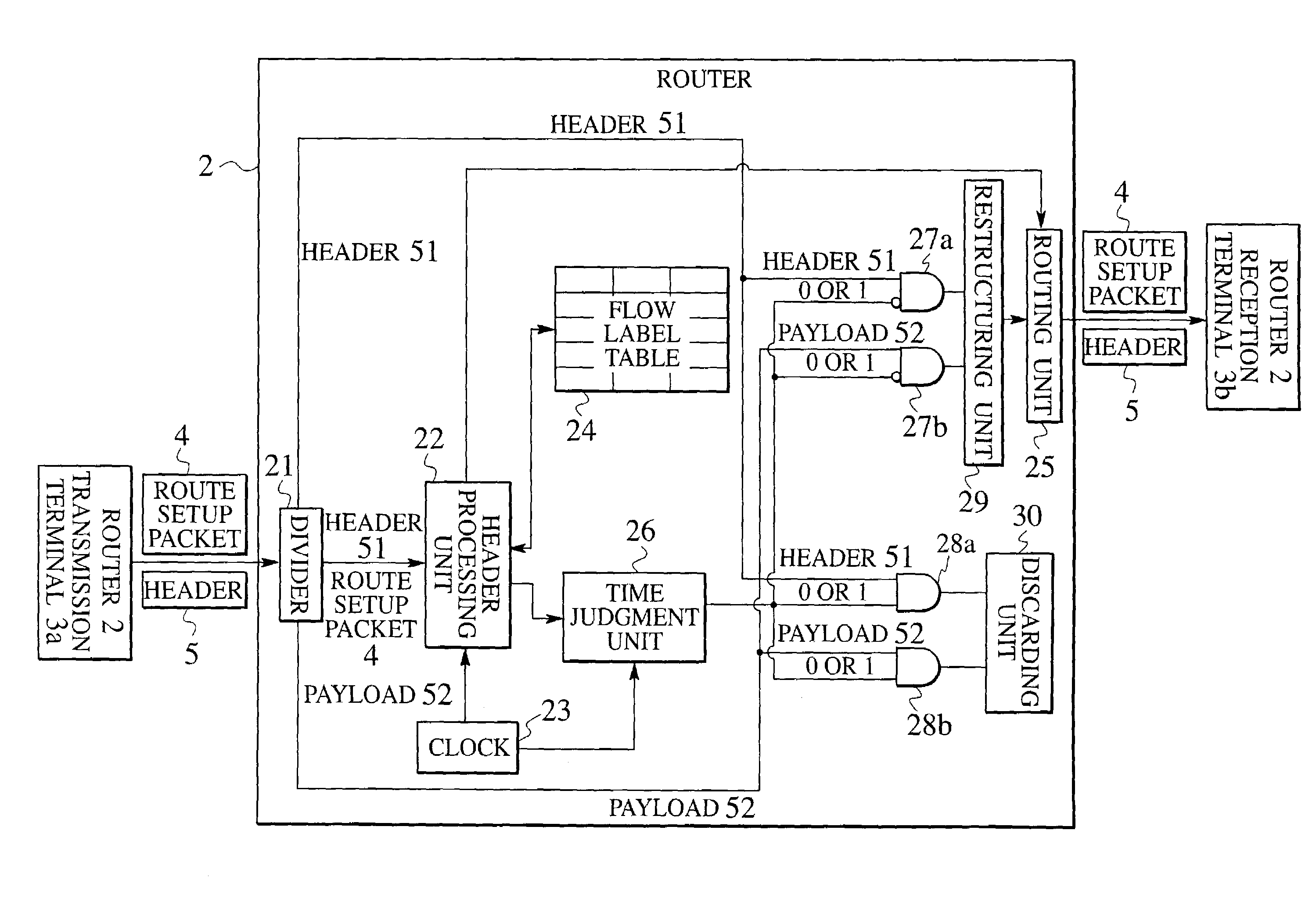
[0028]As shown in FIG. 3, a router 2 includes a divider 21, a header processing unit 22, a clock 23, a flow label table 24, a routing unit 25, a time judgment unit 26, AND circuits 27a, 27b, 28a, and 28b, a restructuring unit 29, and a discarding unit 30. The router 2 functions as routers 2a and 2b shown in FIG. 2.

[0029]The divider 21 receives a packet transmitted from the transmission terminal 3a or another router 2. The packet is either a data packet that includes user data in the transmission terminal 3a ...


PUM


Abstract

A router includes a clock configured to be synchronous to a transmission terminal that transmits a data packet; a comparator configured to compare a delay time of the data packet with an acceptable delay time of the data packet based on the time obtained from the clock; and a packet processing unit configured to either transfer or discard the data packet based on the comparison result of the comparator.

Description

CROSS REFERENCE TO RELATED APPLICATIONS[0001]This application is based upon and claims the benefit of priority from the prior Japanese Patent Applications No. P2001-380677, filed on Dec. 13, 2001; the entire contents of which are incorporated herein by reference.BACKGROUND OF THE INVENTION[0002]1. Field of the Invention[0003]The present invention relates to a router, a terminal apparatus, a communication system, and a routing method.[0004]2. Description of the Related Art[0005]Conventionally, a router 202 shown in FIG. 1 is used as a router that performs transferring of a real time data packet transmitted from a transmission terminal. To begin with, the transmission terminal transmits a route setup packet necessary for setting up a route to transfer the data packet. A divider 221 receives the route setup packet and inputs it to a header processing unit 222. The header processing unit 222 records in a flow label table 223 source address of the transmission terminal, a flow label and ...

Claims


Application Information

Patent Timeline
Patent Type & Authority Patents(United States)
IPC IPC(8): H04J1/16G06F15/16H04L12/28H04L12/70H04L12/46H04L12/841
CPCH04L45/00H04L45/20H04L47/32H04L47/17H04L47/28H04L47/10
Inventor JO, MANHEEHAYASHI, YASUHISAOKAGAWA, TAKATOSHIIHARA, TAKESHI
Owner NTT DOCOMO INC
Why Eureka
Try Eureka