Air cleaner device for motorcycle

a cleaner device and motorcycle technology, applied in the direction of combustion-air/fuel-air treatment, cycle equipment, separation processes, etc., can solve the problems of easy affecting of the airflow taken by the element, inability to improve the efficiency of purification, and inability to quantify the airflow, so as to improve the output of the engine, optimize the direction and the negative pressure of the airflow flowing into the entire element, and improve the effect of purification efficiency

a cleaner device and motorcycle technology, applied in the direction of combustion-air/fuel-air treatment, cycle equipment, separation processes, etc., can solve the problems of easy affecting of the airflow taken by the element, inability to improve the efficiency of purification, and inability to quantify the airflow, so as to improve the output of the engine, optimize the direction and the negative pressure of the airflow flowing into the entire element, and improve the effect of purification efficiency

US7438738B2Inactive Publication Date: 2008-10-21HONDA MOTOR CO LTD

Image

  • Air cleaner device for motorcycle
  • Air cleaner device for motorcycle
  • Air cleaner device for motorcycle

Examples


Embodiment Construction

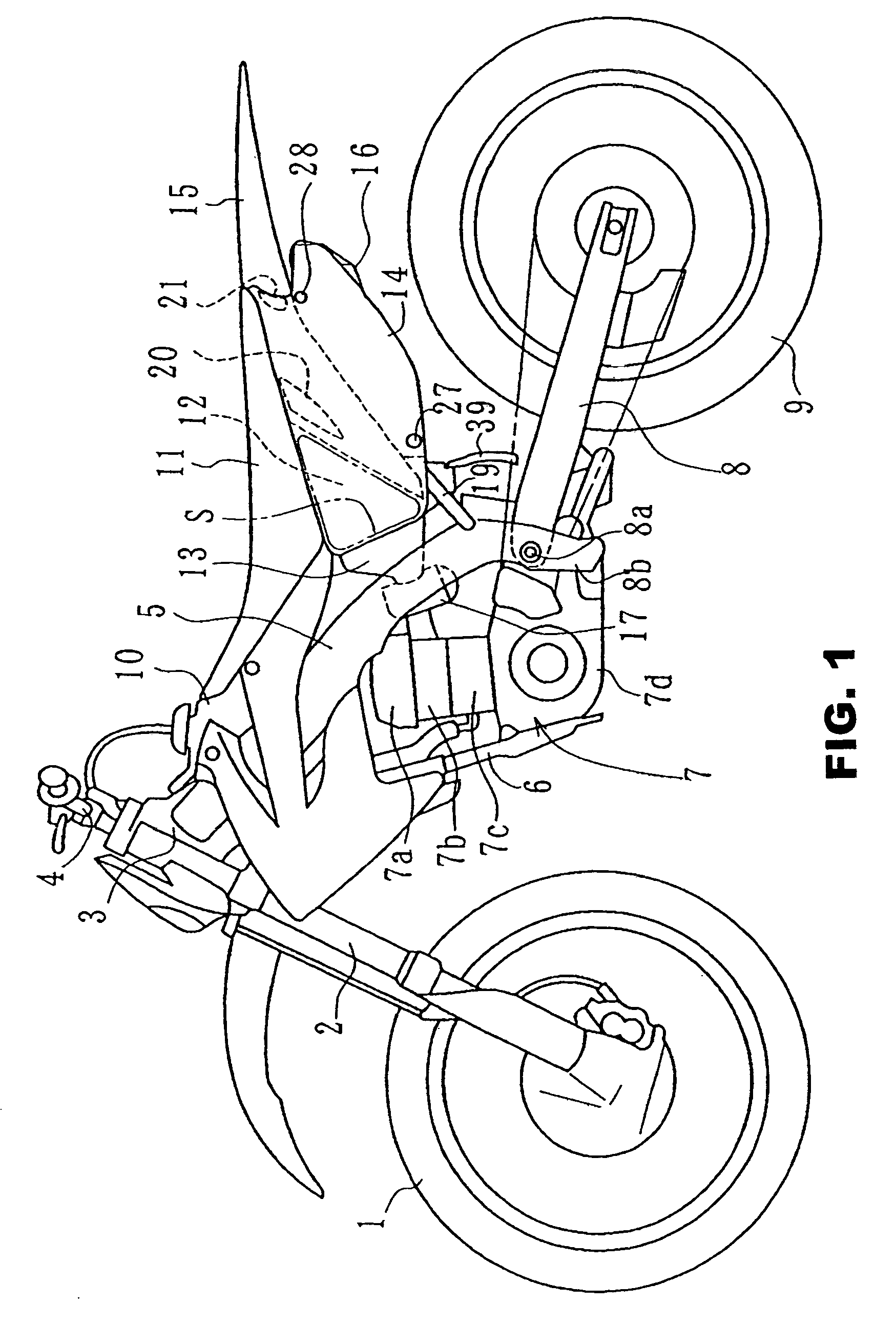
[0023]Referring now to the drawings, an embodiment will be described. FIG. 1 is a left side view of an off-road type motorcycle to which the present invention is applied. Reference numeral 1 in the drawing designates a front wheel, reference numeral 2 designates a pair of left and right front forks for supporting the front wheel 1 from both sides, reference numeral 3 designates a head pipe for steerably journaling the front forks 2, reference numeral 4 designates a handle, reference numeral 5 designates a main frame, reference numeral 6 designates a down frame, reference numeral 7 designates an engine, reference numeral 7a designates a cylinder head cover of the engine, reference numeral 7b designates a cylinder head, reference numeral 7c designates a cylinder, reference numeral 7d designates a crankcase, reference numeral 8 designates a rear arm, reference numeral 8a designates a pivot for pivotably journaling the front end of the rear arm 8 on a pivot plate 8b extending downward f...


PUM

PropertyMeasurementUnit
cylindrical shapeaaaaaaaaaa
pressureaaaaaaaaaa
distanceaaaaaaaaaa

Abstract

An air cleaner device for a motorcycle including a cylindrical filter element disposed in a box of an air cleaner, wherein air purified by the element is sent to an air-intake system. Further, a rectifying member is disposed around the outer periphery of the cylindrical filter element at a predetermined distance apart therefrom and the rectifying member is formed into a cylindrical shape so as to cover the entire outer periphery of the element.

Description

FIELD OF THE INVENTION[0001]The present invention relates to an air cleaner device for a motorcycle and, more specifically, to the same having an air cleaner provided with a cylindrical element.RELATED ART[0002]There is an air cleaner device for a motorcycle including a cylindrical element in a box of an air cleaner disposed below a seat and is adapted to send air purified thereby to a carburetor. It is also known that a portion around the element is partly covered, for example, by an inverted U-shaped rectifying member (See Patent Document JP-A-7-151029).[0003]The rectifying member can rectify airflow with respect to the element. However, since it covers partly in substantially the inverted U-shape, the airflow taken by the element is easily affected by change of a negative pressure of intake air or by a shape of the box of the air cleaner. In other words, although the box of the air cleaner, which is an air-intake vacuum member, sucks outside air in a flow velocity corresponding t...

Claims


Application Information

Patent Timeline
21 Oct 2008
Publication
US7438738B2
IPC
B60K13/02; B62K11/08; F02M35/024; B62J99/00; F02M35/04; F02M35/10; F02M35/16
CPC
F02M35/04; F02M35/10262; F02M35/162; Y02T10/146; Y10S55/30; Y10S55/28; Y02T10/12
Inventors
UNETA, HISASHI; NOGUCHI, YUJI