
Traction control system and method for a vehicle
a technology of traction control system and vehicle, which is applied in the direction of electrical control, tractors, instruments, etc., can solve the problems of operator frustration to the point of turning off the traction control system, the vehicle becoming more entrenched, and the operator being unable to move the vehicle, etc., to achieve better navigation conditions, lower torque, and higher resolution powertrain torque output control
- Summary
- Abstract
- Description
- Claims
- Application Information
AI Technical Summary
Benefits of technology
Problems solved by technology
Method used
Image

Examples
Embodiment Construction
[0016]Traction control systems may be used to adjust powertrain output to improve vehicle operation in situations that may result in reduced traction between a vehicle's wheel and the road. As noted above, a non-moving vehicle situation can be especially challenging where even limiting powertrain output and controlling wheel slip may not result in any significant movement of the vehicle. The following disclosure addresses such a situation, as well as others.
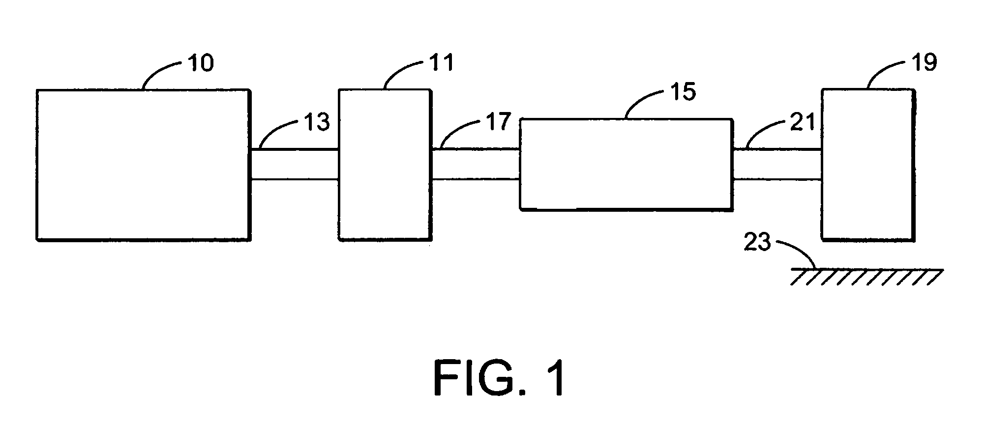
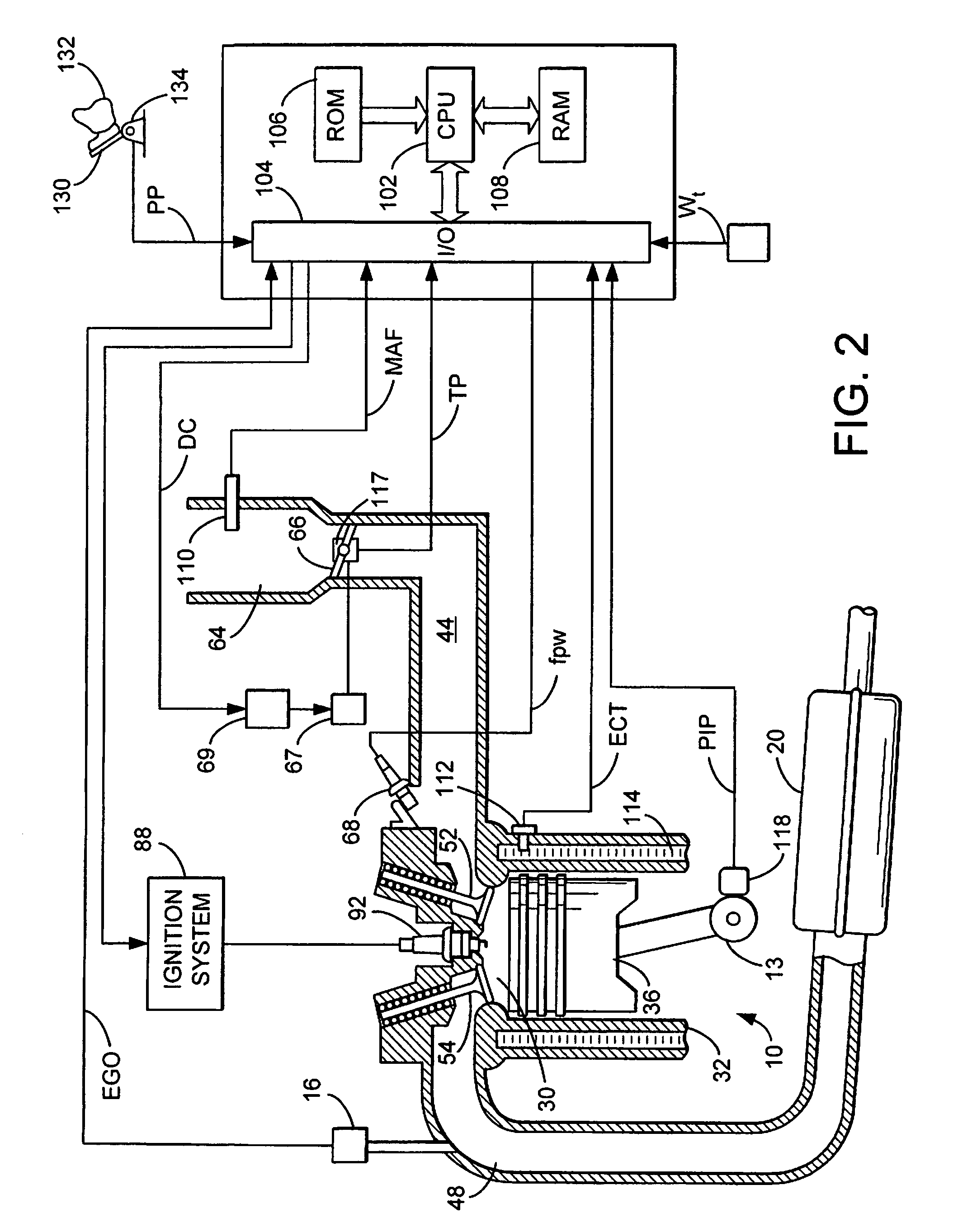
[0017]Referring to FIG. 1 an example powertrain of a vehicle is shown. Specifically, internal combustion engine 10, further described herein with particular reference to FIG. 2, is shown coupled to torque converter 11 via crankshaft 13. Torque converter 11 may also coupled to transmission 15 via transmission input shaft 17. Torque converter 11 may have a bypass clutch, which can be engaged, disengaged, or partially engaged. When the clutch is either disengaged or partially engaged, the torque converter is said to be in an unlocke...
PUM
 Abstract
Description
Claims
Application Information