Traction control system and method for a vehicle

a technology of traction control system and vehicle, which is applied in the direction of electrical control, tractors, instruments, etc., can solve the problems of operator frustration to the point of turning off the traction control system, the vehicle becoming more entrenched, and the operator being unable to move the vehicle, etc., to achieve better navigation conditions, lower torque, and higher resolution powertrain torque output control

Active Publication Date: 2006-04-13
FORD GLOBAL TECH LLC
View PDF17 Cites 36 Cited by
  • Summary
  • Abstract
  • Description
  • Claims
  • Application Information

AI Technical Summary

Benefits of technology

[0008] In this way, if overriding driver actuation to perform traction control still results in a non-moving vehicle condition, for example, the traction management system can return control to the driver, but with finer resolution at lower torques to better navigate the condition. In other words, in one example, the vehicle's powertrain response behavior to a command input may be modified if a non-moving condition is identified in order to provide the driver higher resolution powertrain torque output control. In this way, improved vehicle performance may be achieved, and improved customer satisfaction obtained.
[0009] In one example, once the vehicle is moving a sufficient amount, the vehicle vehicle's powertrain response behavior can be returned to that which corresponds to a moving vehicle. This transition may be gradual, in one example, so that driver perception of the transition may be reduced.

Problems solved by technology

Some of the most challenging tasks for current Traction Control (TC) systems include situations where a vehicle is “stuck” in (deep) snow or mud, or on a possibly icy and / or inclined road.
However, the inventors herein have recognized potential issues with such approaches.
For example, the use of solely higher slip may actually cause the vehicle to become more entrenched and reduce the ability of the operator to move the vehicle.
Also, in continuing traction control intervention that still may not move the vehicle, the operator may become frustrated to the point of turning the traction control system off, and trying to negotiate the situation without traction control active.
These issues may lead to decreased customer satisfaction.

Method used


Image

  • Traction control system and method for a vehicle
  • Traction control system and method for a vehicle
  • Traction control system and method for a vehicle

Examples


Embodiment Construction

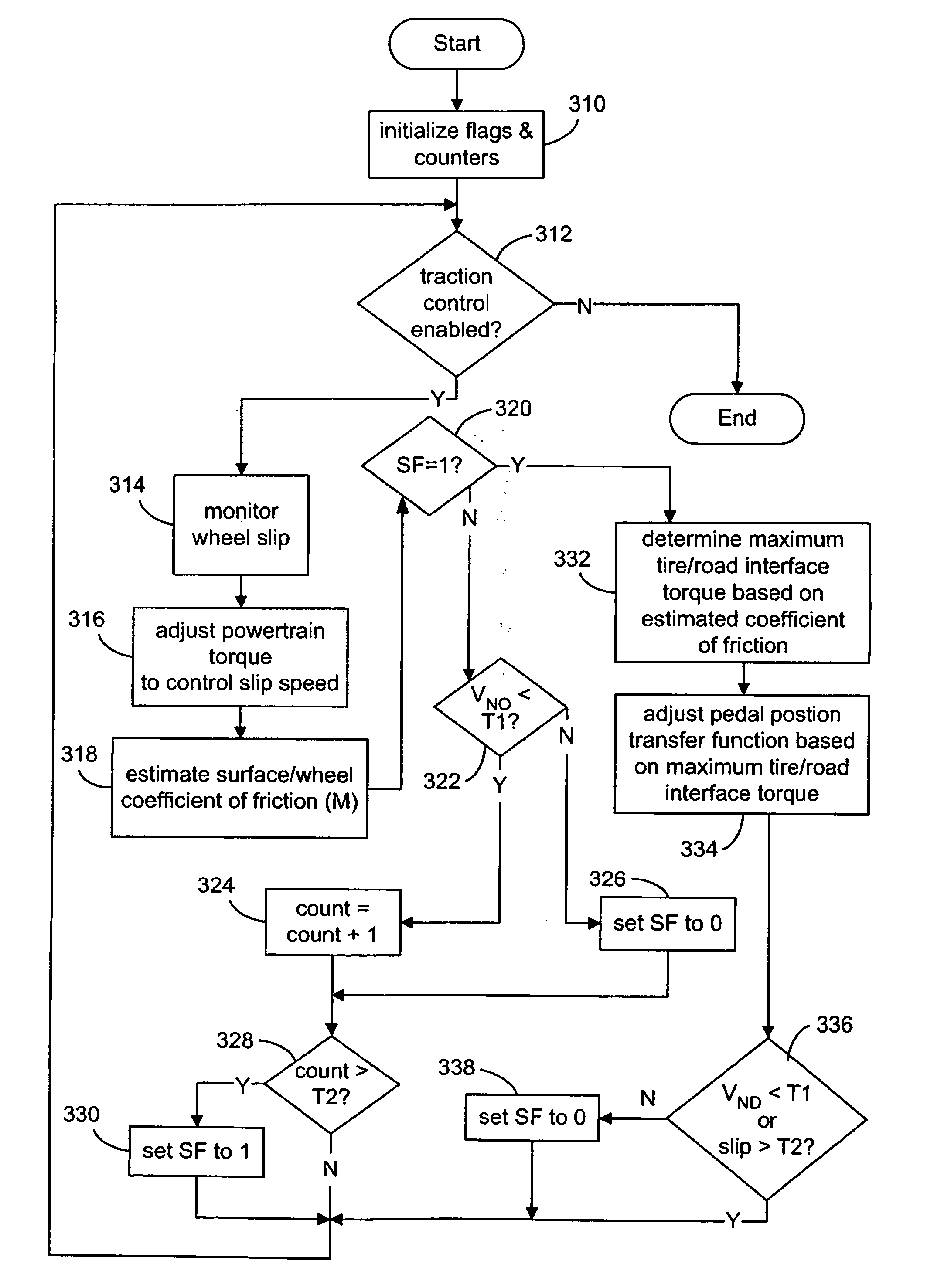
[0016] Traction control systems may be used to adjust powertrain output to improve vehicle operation in situations that may result in reduced traction between a vehicle's wheel and the road. As noted above, a non-moving vehicle situation can be especially challenging where even limiting powertrain output and controlling wheel slip may not result in any significant movement of the vehicle. The following disclosure addresses such a situation, as well as others.

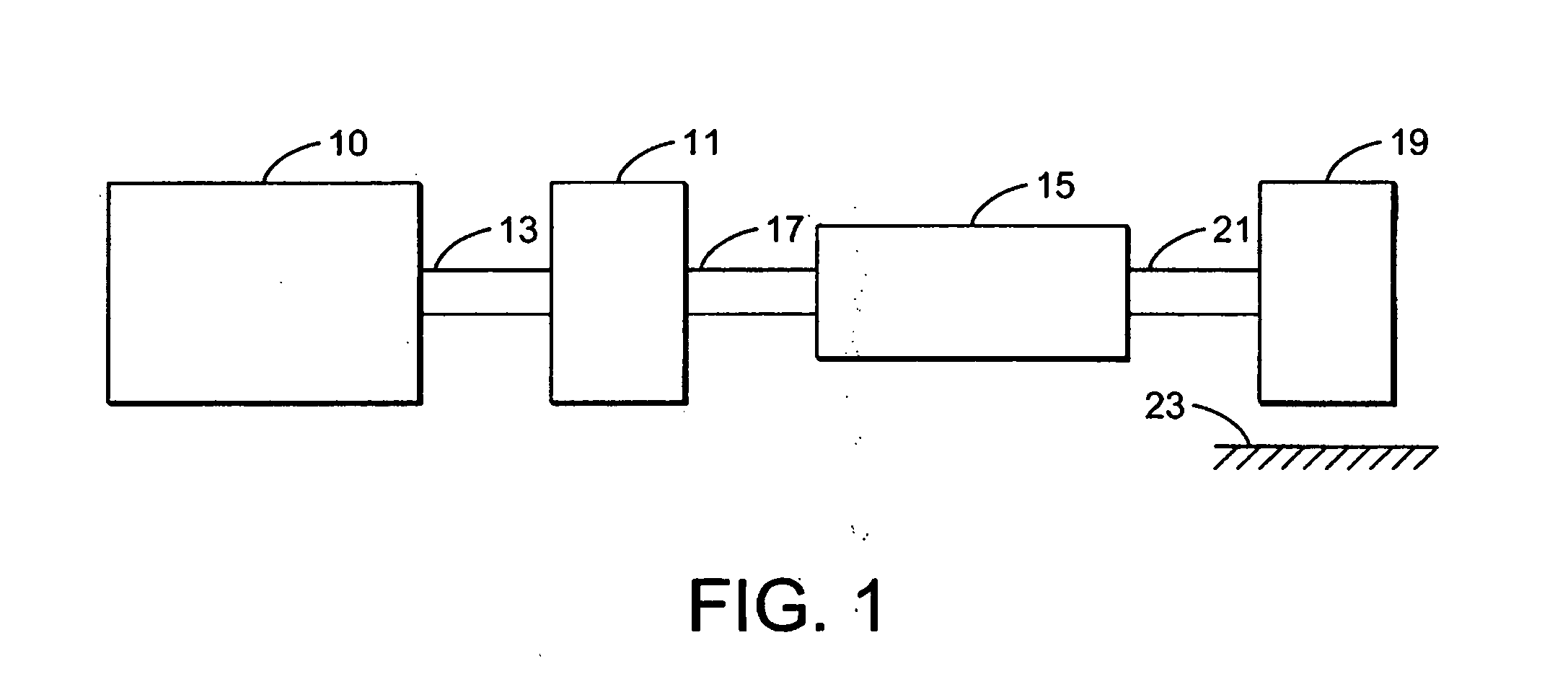
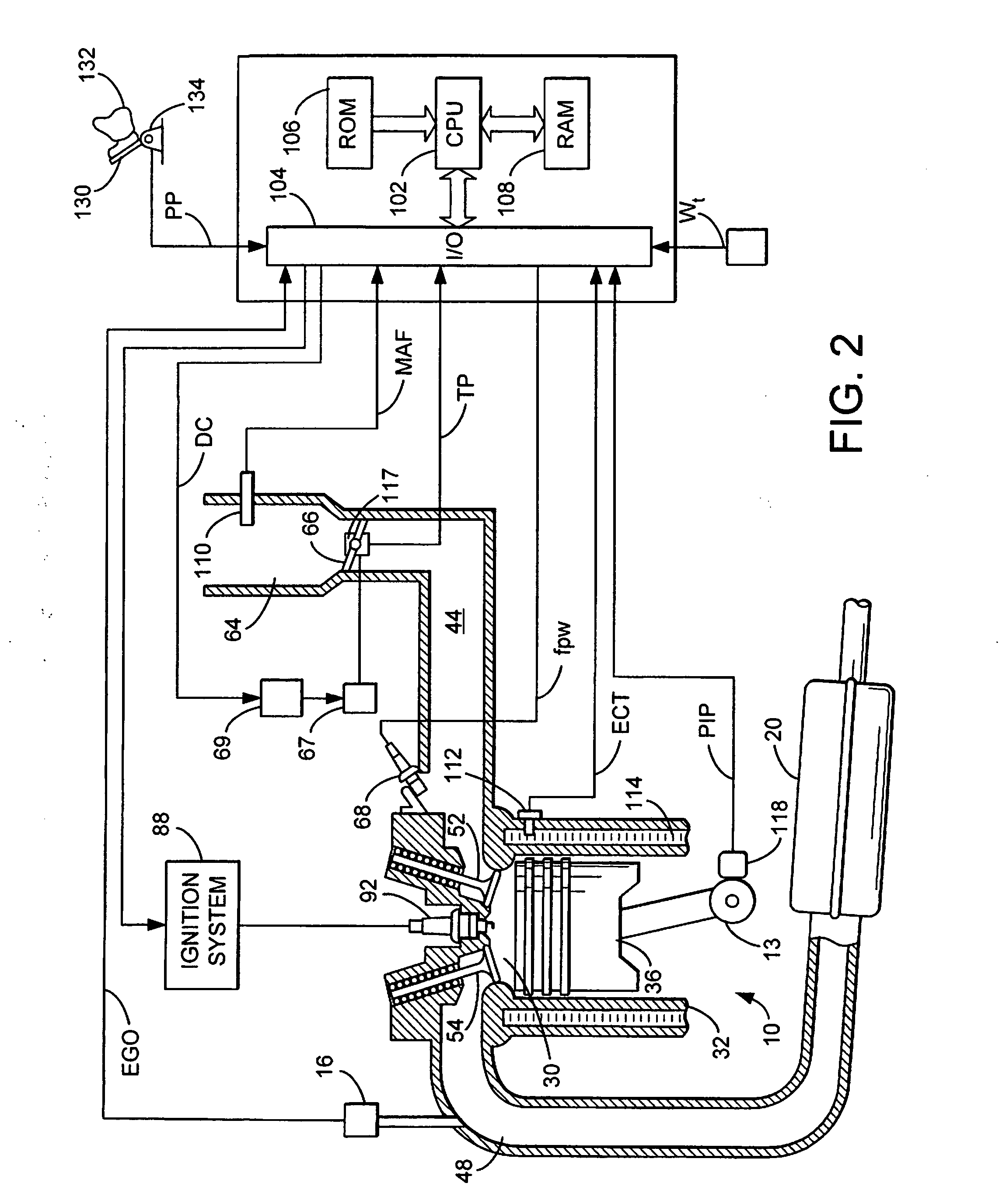
[0017] Referring to FIG. 1 an example powertrain of a vehicle is shown. Specifically, internal combustion engine 10, further described herein with particular reference to FIG. 2, is shown coupled to torque converter 11 via crankshaft 13. Torque converter 11 may also coupled to transmission 15 via transmission input shaft 17. Torque converter 11 may have a bypass clutch (described in FIGS. 20-23), which can be engaged, disengaged, or partially engaged. When the clutch is either disengaged or partially engaged, the torque convert...


PUM


Abstract

In one example, A method for controlling a powertrain of a vehicle with wheels, the vehicle having a pedal actuated by a driver, is described. The method may include generating powertrain torque transmitted to the wheels in a first relation to actuation of the pedal by the driver during a first condition where said transmitted torque causes said wheels to slip relative to a surface; overriding said driver actuated powertrain torque to control said slip; and during a second condition after said first condition where said vehicle is moving less than a threshold, generating powertrain torque transmitted to the wheels in a second relation to actuation of the pedal by the driver, where for a given pedal position, less powertrain torque is transmitted with said second relation compared to said first relation.

Description

BACKGROUND AND SUMMARY [0001] Some of the most challenging tasks for current Traction Control (TC) systems include situations where a vehicle is “stuck” in (deep) snow or mud, or on a possibly icy and / or inclined road. [0002] One approach to vehicle traction control in non-moving conditions is described in U.S. Pat. No. 5,265,693. In this example, higher slip may be used if controller senses a non-moving (stuck) vehicle. In another approach, (U.S. Pat. No. 5,735,362), the controller uses a combination of a controlled increase in target wheel slip and subsequent phases that reduces driving power and torque to the wheels. [0003] However, the inventors herein have recognized potential issues with such approaches. For example, the use of solely higher slip may actually cause the vehicle to become more entrenched and reduce the ability of the operator to move the vehicle. Also, in continuing traction control intervention that still may not move the vehicle, the operator may become frustr...

Claims


Application Information

Patent Timeline
Patent Type & Authority Applications(United States)
IPC IPC(8): G06F17/00
CPCB60K28/16B60W2540/12B60W2550/148B60W2710/0605Y10T477/675F02D41/021F02D2250/18Y10T477/688Y10T477/679F02D11/105B60W2552/40
Inventor HROVAT, DAVORFODOR, MICHAELMCCONNELL, MITCH
Owner FORD GLOBAL TECH LLC
Why Eureka
Try Eureka