Video buffer control apparatus for dual video decoding and digital broadcasting receiver thereof

a video decoding and buffer control technology, applied in the field of digital broadcasting receivers for dual video decoding, can solve problems such as buffer delay consideration, and achieve the effect of simplified dual video decoding and efficient control

Inactive Publication Date: 2009-10-27
LG ELECTRONICS INC
View PDF7 Cites 17 Cited by
  • Summary
  • Abstract
  • Description
  • Claims
  • Application Information

AI Technical Summary

Benefits of technology

[0019]An object of the present invention is to provide a video buffer control apparatus for dual video decoding and digital broadcasting receiver thereof, by which a configuration of a video buffer control unit in the digital broadcasting receiver having dual video decoders is simplified.
[0020]Another object of the present invention is to provide a video buffer control apparatus for dual video decoding and digital broadcasting receiver thereof, in which a video buffer is efficiently controlled with minimum hardware in the digital broadcasting receiver allocating a video buffer to an external memory to support the dual video decoding.

Problems solved by technology

Yet, a buffer delay considered by the MPEG encoder of the transmitting side occurs until the video stream is decoded by the video decoder to be displayed.

Method used


Image

  • Video buffer control apparatus for dual video decoding and digital broadcasting receiver thereof
  • Video buffer control apparatus for dual video decoding and digital broadcasting receiver thereof
  • Video buffer control apparatus for dual video decoding and digital broadcasting receiver thereof

Examples


Embodiment Construction

[0030]Reference will now be made in detail to the preferred embodiments of the present invention, examples of which are illustrated in the accompanying drawings. Wherever possible, the same reference numbers will be used throughout the drawings to refer to the same or like parts.

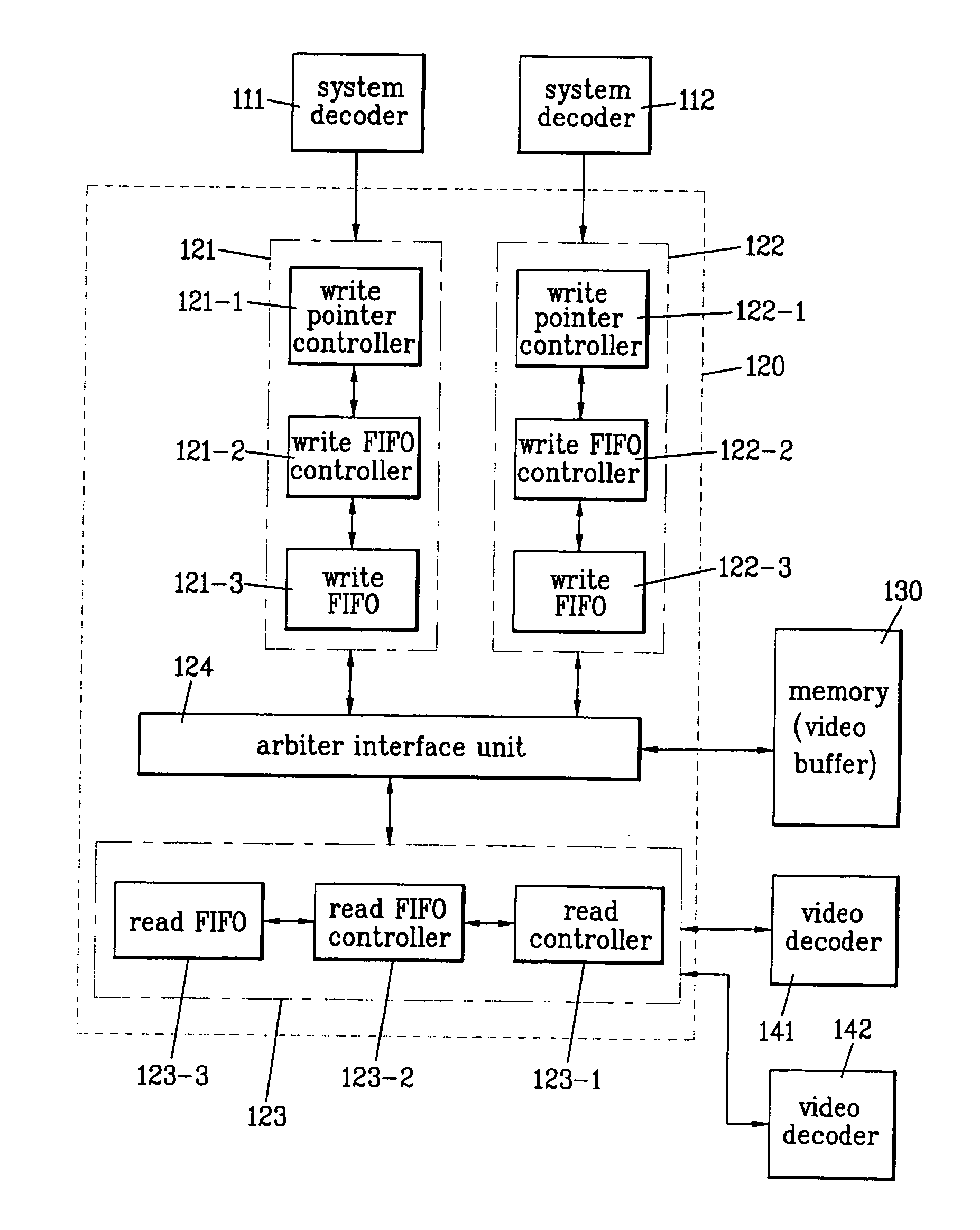
[0031]FIG. 1 is a block diagram of a video buffer control apparatus for dual video decoding according to the present invention.

[0032]Referring to FIG. 1, a video buffer control unit 120 includes a pair of write units 121 and 122, a read unit 123, and an arbiter interface unit 124. For convenience of the description of the present invention, a reference number ‘121’ indicates a first write unit and a reference number ‘122’ indicates a second write unit.

[0033]And, one or two system decoders can be provided to separate audio / video / additional data streams from a multiplexed TP stream. For instance, if there exist two tuners, two system decoders are provided. If a plurality of programs are multiplexed on one chan...


PUM


Abstract

The present invention provides a video buffer control apparatus for dual video decoding and digital broadcasting receiver. In the present invention, one read block controls the reading of at least two video buffers in performing video decoding on at least two channels, whereby the video buffers can be efficiently controlled and whereby the hardware size of the video buffer control apparatus can be reduced. Moreover, the present invention can simultaneously decode both of the digital broadcasting and a video clip or MPEG still picture having a data format inputted via path different from that of the digital broadcasting.

Description

[0001]This application claims the benefit of the Korean Application No. 10-2004-0005059 filed on Jan. 27, 2004, which is hereby incorporated by reference.BACKGROUND OF THE INVENTION[0002]1. Field of the Invention[0003]The present invention relates to a digital broadcasting receiver for dual video decoding, and more particularly, to a video buffer control apparatus for dual video decoding of an MPEG2 video decoder.[0004]2. Discussion of the Related Art[0005]Currently, it is a worldwide tendency for digital broadcasting that is already on-air or is ready to launch. Mostly, the digital broadcasting adopts MPEG2 (moving picture experts group 2) as a video standard. An interlacing video mode specification having 1920 (pixels)*1080 (lines) or a progressive mode specification having 1280 (pixels)*720 (lines) corresponds to a main profile high level (MP@HL) specification of MPEG2.[0006]In such a case, a bit rate after compression can have a value close to 20 M / sec. And, a corresponding comp...

Claims


Application Information

Patent Timeline
Patent Type & Authority Patents(United States)
IPC IPC(8): H04N7/12H04N7/24
CPCH04N21/44004H04N21/23406A63H33/42B42F7/14B42P2201/08B42P2221/00
Inventor CHUNG, TAE IL
Owner LG ELECTRONICS INC
Why Eureka
Try Eureka