Mounting mechanisms for pedicle screws and related assemblies

a technology of mounting mechanism and pedicle screw, which is applied in the field of advantages, can solve the problems of accelerating degeneration at those levels, reducing range of motion, and affecting the treatment of low back pain, and achieves the effects of improving treatment efficiency, improving treatment efficiency, and improving treatment efficiency

Active Publication Date: 2009-11-10
RACHIOTEK
View PDF97 Cites 190 Cited by
  • Summary
  • Abstract
  • Description
  • Claims
  • Application Information

AI Technical Summary

Benefits of technology

[0013]According to the present disclosure, advantageous devices, systems and methods for spinal stabilization are provided. According to preferred embodiments of the present disclosure, the disclosed devices, systems and methods provide dynamic stabilization to the spine so as to provide clinically efficacious results. In addition, the disclosed devices, systems and methods offer clinical advantages, including ease of installation, versatility / flexibility in application, and superior clinical results for individuals encountering lower back pain and other spine-related difficulties.
[0014]According to exemplary implementations of the present disclosure, devices, systems and methods are provided that encompass one or more pedicle screws for attachment to spinal structures. The pedicle screw(s) of the present disclosure are typically employed as part of a spine stabilization system that includes one or more of the following advantageous structural and / or functional attributes:
[0018]Advantageous installation accessories (e.g., cone structures) for facilitating placement / installation of spine stabilization system components, such accessories being particularly adapted for use with conventional guidewire(s) to facilitate alignment / positioning of system components relative to the pedicle screw;
[0020]Advantageous dynamic spine stabilization connection systems that facilitate substantially rigid attachment of an elongated member (e.g., a rod) relative to the pedicle screw while simultaneously facilitating movement relative to adjacent structures (e.g., an adjacent pedicle screw) to permit easy and efficacious intra-operative system placement;
[0021]An advantageous “pre-load” arrangement for a securing structure (e.g., a set screw) that may be used in situ to mount a ball joint or other accessory component relative to the pedicle screw, thereby minimizing the potential for clinical difficulties associated with location and / or alignment of such securing structure(s).
[0023]Generally, the structures / functions of the threaded shaft portions of the pedicle screws disclosed herein are of conventional design. Thus, installation of the pedicle screws is generally undertaken by a clinician in a conventional manner. Selection and placement of the pedicle screws is generally based on conventional criteria, as are known to persons skilled in the art. However, unlike conventional pedicle-screw based systems, the devices, systems, and methods of the present disclosure offer advantageous clinical results, e.g., based on ease and flexibility of rod / elongated member placement, dynamic attributes of the rod / elongated member in situ relative to the pedicle screws, and / or dynamic force delivery in response to spinal displacement stimulus.

Problems solved by technology

Low back pain is one of the most expensive diseases afflicting industrialized societies.
While fusion is effective about seventy percent of the time, there are consequences even to these successful procedures, including a reduced range of motion and an increased load transfer to adjacent levels of the spine, which may accelerate degeneration at those levels.
Further, a significant number of back-pain patients, estimated to exceed seven million in the U.S., simply endure chronic low-back pain, rather than risk procedures that may not be appropriate or effective in alleviating their symptoms.
Clinical studies have also found that range of motion does not correlate well with low back pain.

Method used


Image

  • Mounting mechanisms for pedicle screws and related assemblies
  • Mounting mechanisms for pedicle screws and related assemblies
  • Mounting mechanisms for pedicle screws and related assemblies

Examples


Embodiment Construction

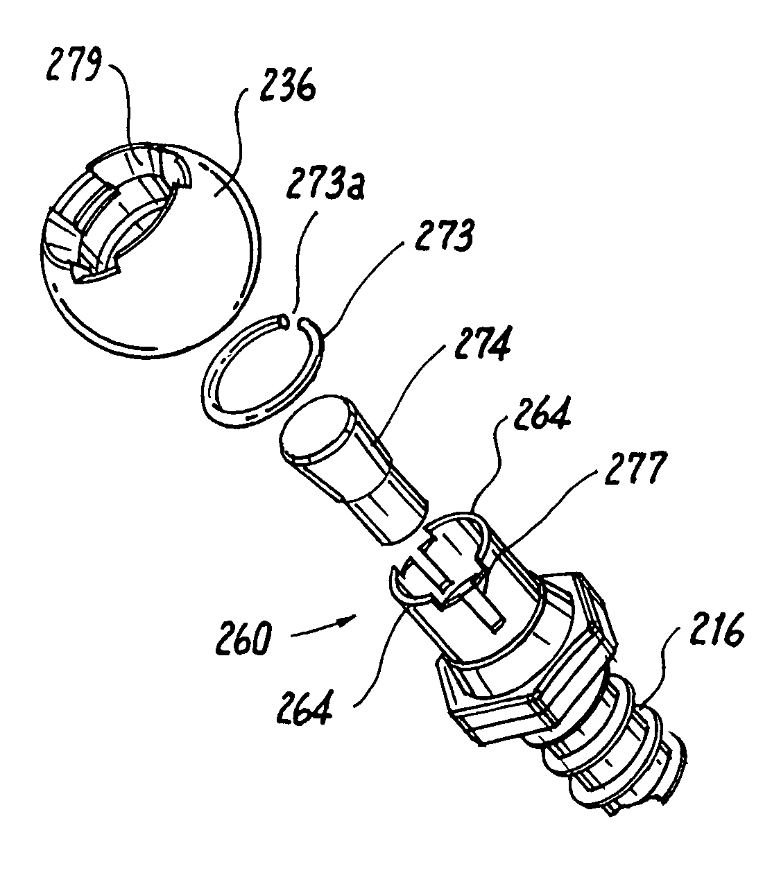
[0060]The present disclosure provides advantageous devices, systems and methods for spinal stabilization and / or alternative surgical implant applications. More particularly, the present disclosure provides devices, systems and methods that deliver dynamic stabilization to the spine so as to provide clinically efficacious results. The exemplary embodiments disclosed herein are illustrative of the advantageous spine stabilization systems and surgical implants of the present disclosure, and methods / techniques for implementation thereof. It should be understood, however, that the disclosed embodiments are merely exemplary of the present invention, which may be embodied in various forms. Therefore, the details disclosed herein with reference to exemplary dynamic spinal stabilization systems and associated methods / techniques are not to be interpreted as limiting, but merely as the basis for teaching one skilled in the art how to make and / or use the advantageous dynamic spinal stabilizatio...


PUM


Abstract

A pedicle screw is provided that includes an upwardly extending collet. The collet may include downwardly extending slots that define deflectable segments therebetween. When a spherical element or other structure, e.g., a non-dynamic stabilizing element, is positioned around the collet, introduction of a set screw causes outward deflection of the upstanding segments into engagement with the spherical element. A snap ring may be interposed between the collet and the spherical element to facilitate positioning therebetween. In an alternative embodiment, a non-slotted collet is employed. In such embodiment, the collet and the spherical element may be threadingly engaged and may include a snap ring therebetween. The pedicle screw subassemblies may be incorporated into a spinal stabilization system which may include a dynamic stabilizing member to provide clinically efficacious results.

Description

CROSS REFERENCE TO RELATED APPLICATIONS[0001]The present application claims the benefit of a provisional application entitled “Dynamic Spine Stabilization,” filed on Jun. 23, 2004 and assigned Ser. No. 60 / 581,716. In addition, the foregoing provisional patent applications is incorporated in its entirety herein by reference to the extent not inconsistent herewith.BACKGROUND OF THE INVENTION[0002]1. Technical Field[0003]The present disclosure relates to advantageous methods and apparatus for spinal stabilization. More particularly, the present disclosure relates to methods and apparatus for providing dynamic stabilization to the spine so as to provide clinically efficacious results.[0004]2. Background Art[0005]Low back pain is one of the most expensive diseases afflicting industrialized societies. With the exception of the common cold, it accounts for more doctor visits than any other ailment. The spectrum of low back pain is wide, ranging from periods of intense disabling pain which ...

Claims


Application Information

Patent Timeline
Patent Type & Authority Patents(United States)
IPC IPC(8): A61B17/70A61B17/58A61B17/56A61B17/88
CPCA61B17/7007A61B17/7025A61B17/7028A61B17/704A61B17/8685A61B17/7004A61B17/7011A61B17/7035A61B2017/00991A61B17/7041A61B17/705A61B17/7076A61B17/7083A61B17/7037
Inventor TIMM, JENS PETERHILDEBRAND, BRYANCALLAHAN, RONALDCORRAO, ERNESTMAGUIRE, STEPHENWALTERS, CARMEN
Owner RACHIOTEK
Why Eureka
Try Eureka