Fuel injection system

a fuel injection system and fuel technology, applied in the direction of liquid fuel feeders, combustion air/fuel air treatment, machines/engines, etc., can solve the problems of increasing the cost of production, and increasing the heat of a1 and other directions, to achieve the effect of increasing the starting reliability, improving the idling quality of the engine, and increasing the starting reliability

Inactive Publication Date: 2010-03-02
ROBERT BOSCH GMBH
View PDF16 Cites 25 Cited by
  • Summary
  • Abstract
  • Description
  • Claims
  • Application Information

AI Technical Summary

Benefits of technology

[0009]An advantage of the present invention is that the heating concept of the inventive fuel injection system is independent of the control-unit platform and of the type of fuel injector used, since the heatable adapter can be inserted into a direct-injection fuel injector and into a fuel injector for manifold injection.
[0010]This results in the advantage that the individual components of the inventive fuel injection system can also be marketed for foreign systems.
[0011]A further advantage of the present invention is increased starting reliability, in particular when fuels containing ethanol are used, because the fuel is heated as a function of the fuel temperature.
[0012]A further advantage of the inventive fuel injector is the fact that, in the cold state, the idling quality of the engine is improved by heating the fuel using the inventive fuel injection system.
[0013]It is also an advantage that the fuel can be heated independently of the start of the engine or the actuation of the ignition.
[0014]The fuel injection system described in the present invention is simple, robust, and flexible; it therefore also results in a cost-optimizing effect in production.

Problems solved by technology

The disadvantage is that the fuel in the fuel injector described in DE 196 29 589 A1 is also heated when it has a temperature that is already high enough for combustion.
As a result, it is possible that too much thermal energy will be supplied to the fuel.
A further disadvantage is the fact that a Peltier element is provided as a heat pump to heat the fuel in the fuel injector; it is relatively cost-intensive and, when used in the fuel injector, it requires a large quantity of electrical power.
The disadvantage is that a fuel injector is provided for the cold-start and warm-up device described, which includes an electrically operated heater core which is permanently installed in the inlet fitting.

Method used


Image

  • Fuel injection system
  • Fuel injection system

Examples


Embodiment Construction

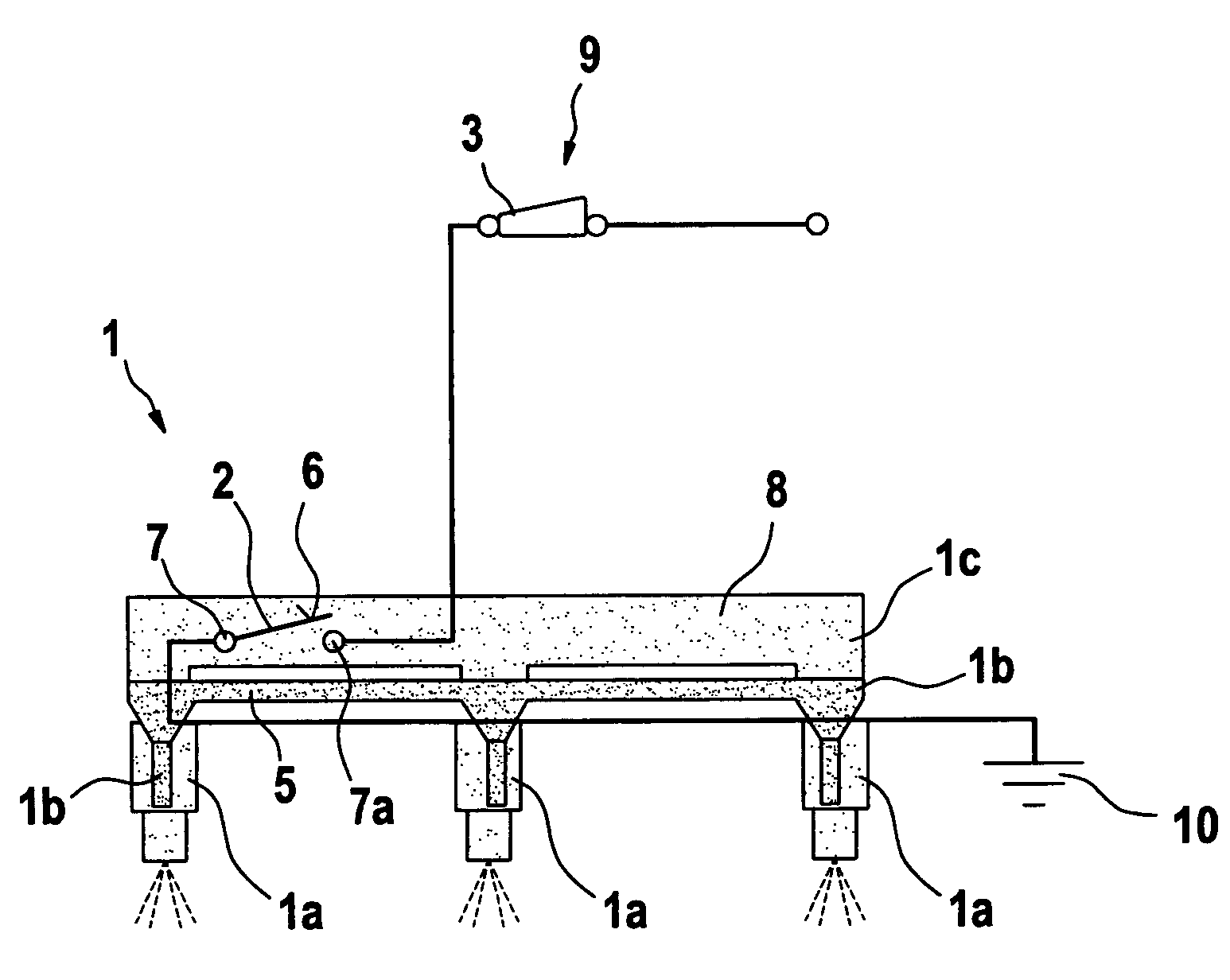
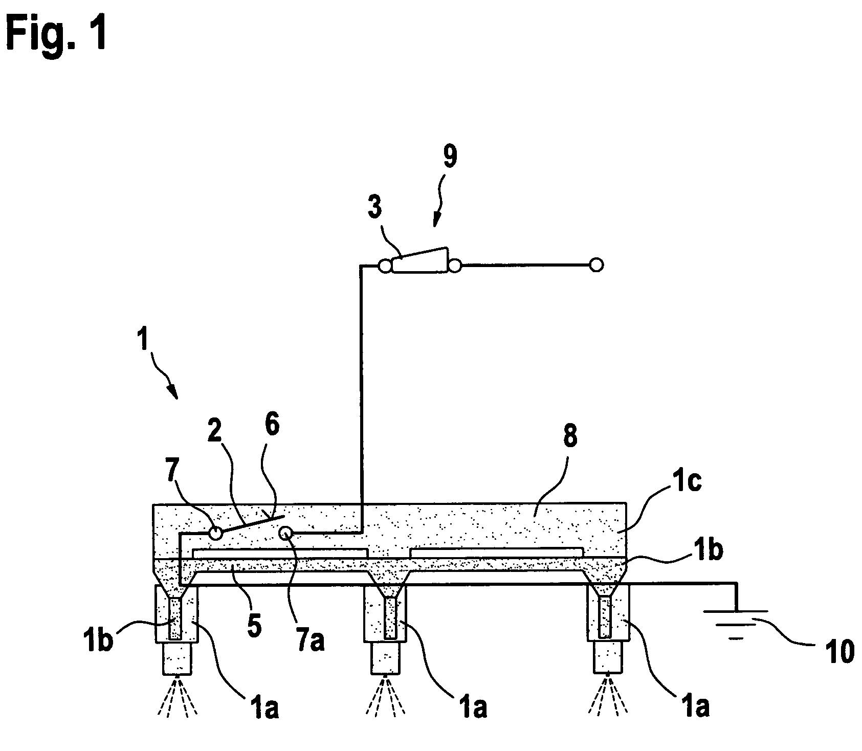
[0019]FIG. 1 shows an inventive fuel injection system 1 with at least one fuel injector 1a and a heatable adapter 1b, which is connected to a fuel rail 1c and to fuel injector 1a of fuel injection system 1; a thermoswitch 2 is provided in fuel rail 1c, which is connected with a device 3 which establishes external contact, and with heatable adapter 1b.

[0020]Thermoschalter 2 includes a thermosensor, which triggers a switching procedure of thermoswitch 2 when fuel 8 located in fuel rail 1c has a temperature that is below a specified threshold temperature. Thermoswitch 2 itself can be designed as a bimetallic strip or a thermistor. Electrical heating elements 5 are provided in heatable adapter 1b; they heat fuel 8 that flows from fuel rail 1c into related fuel injector 1a. Heating fuel 8 is advantageous when atomized fuel 8 would condense on the cold combustion chamber wall because the combustion chamber had become cold.

[0021]Thermoswitch 2 is composed of a pressure-resistant material ...


PUM


Abstract

A fuel injection system (1) with at least one fuel injector (1a) and a heatable adapter (1b), which is connected to a fuel rail (1c) and to the fuel injector (1a) of the fuel injection system (1); a thermoswitch (2) is provided in the fuel rail (1c), which is connected with an external door contact switch (3) and with the heatable adapter (1b). The thermoswitch (2) includes a thermosensor, so that a reliable cold start is ensured by the fact that, when a previously specified fuel temperature is fallen below, the thermoswitch (2) switches over and causes fuel (8) to be heated.

Description

CROSS-REFERENCE TO RELATED APPLICATION[0001]The invention described and claimed herein below is also described in German Patent Application DE 10 2005 036 952.9 filed on Aug. 5, 2009. This German Patent Application, whose subject matter is incorporated here by reference, provides the basis for a claim of priority of invention under 35 U.S.C. 119(a)-(d).BACKGROUND OF THE INVENTION[0002]The present invention relates to a fuel injection system.[0003]The related art refers to, e.g., a fuel injector with a heating device for heating the fuel on its discharge side, as described in DE 196 29 589 A1. In the fuel injector described in DE 196 29 589 A1, the power loss of the energized solenoid coil is used to heat the fuel, and, as the heat-exchange section, a Peltier element which functions as a heat pump is provided; the Peltier element includes the nozzle needle and the fuel inside it.[0004]The disadvantage is that the fuel in the fuel injector described in DE 196 29 589 A1 is also heated ...

Claims


Application Information

Patent Timeline
Patent Type & Authority Patents(United States)
IPC IPC(8): F02M69/46F02M69/50
CPCF02M31/125F02M53/02F02M53/06F02M55/025F02M2200/24Y02T10/126Y02T10/12F02M55/02
Inventor HAAG, GOTTLOBPOSSELT, ANDREASLORENZ, MARKO
Owner ROBERT BOSCH GMBH
Why Eureka
Try Eureka