Balun transformer with improved harmonic suppression

a transformer and harmonic suppression technology, applied in the field of electronic assemblies, can solve the problems of increasing the overall size needed for the balun, increasing the insertion loss, and increasing the manufacturing cost of the system, so as to reduce the impact on the overall size and manufacturing cost of the device, improve the overall performance of the device, and reduce the effect of insertion loss

Active Publication Date: 2010-03-23
NXP USA INC
View PDF5 Cites 23 Cited by
  • Summary
  • Abstract
  • Description
  • Claims
  • Application Information

AI Technical Summary

Benefits of technology

[0018]In one embodiment, the mid-point of the secondary winding of the balun transformer is connected to ground through reactive components (e.g., an inductor, a capacitor, or a combination thereof) that cause the circuit to resonate at the second harmonic of the fundamental frequency of the balun. The values of the added reactive components are such that when combined with the existing balun, they generate a resonance, thus a notch, in the output signal at the second harmonic frequency. As such, second harmonic suppression is significantly improved.
[0030]One advantage of the electronic assembly described above is that the reactive components within the reaction circuit cause the balun transformer to resonate at the second harmonic (or other selected harmonic) of its fundamental frequency. As a result, second harmonic rejection performance, as well as the overall performance of the device, is significantly improved. Another advantage is that the reactive components of the reaction circuit may be formed using conventional semiconductor processing steps and thus integrated with the other components of the device. Thus, the impact on the overall size and manufacturing costs of the device is minimized.

Problems solved by technology

However, such harmonic filters typically increase the insertion loss, as well as the manufacturing costs, of the system and increase the overall size needed for the balun.

Method used


Image

  • Balun transformer with improved harmonic suppression
  • Balun transformer with improved harmonic suppression
  • Balun transformer with improved harmonic suppression

Examples


Embodiment Construction

[0016]The following detailed description is merely exemplary in nature and is not intended to limit the invention or application and uses of the invention. Furthermore, there is no intention to be bound by any expressed or implied theory presented in the preceding technical field, background, brief summary, or the following detailed description. It should also be noted that FIGS. 1-9 are merely illustrative and may not be drawn to scale.

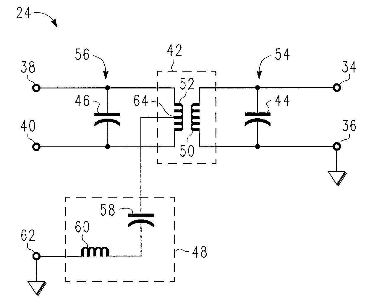
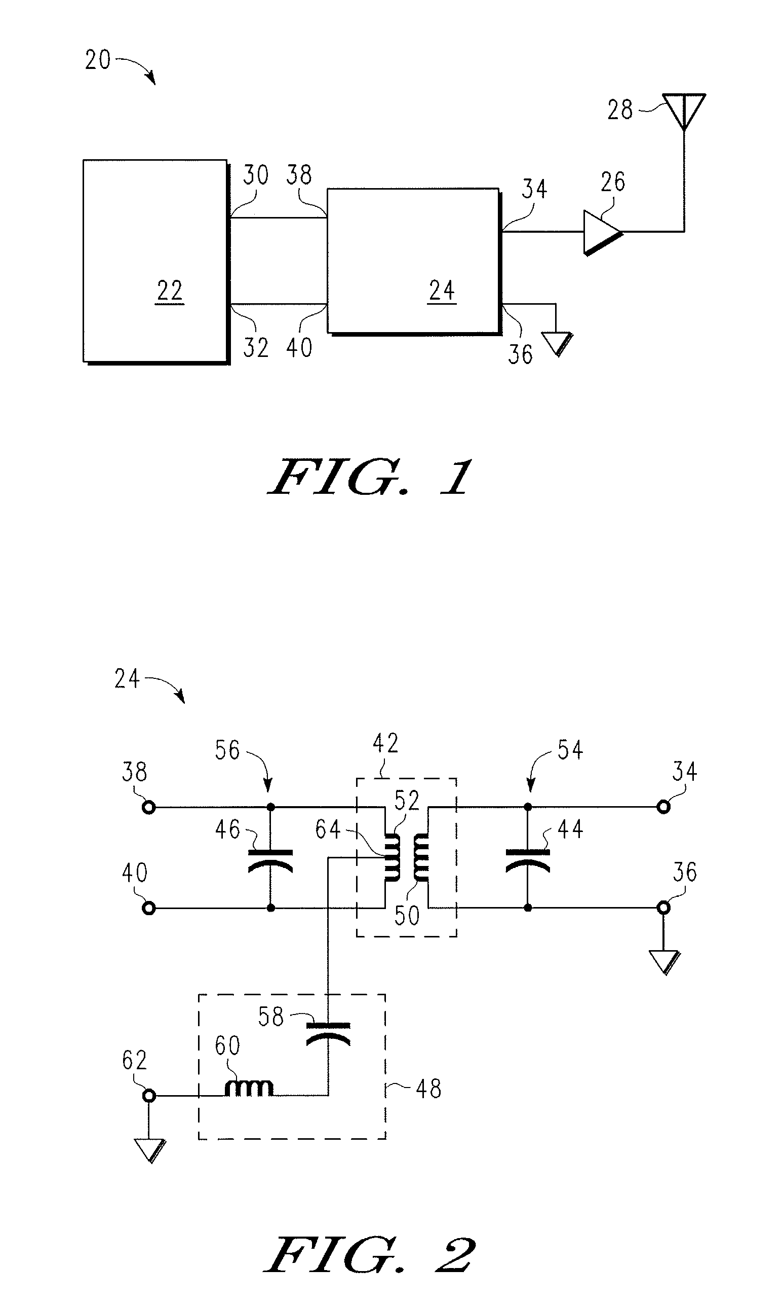
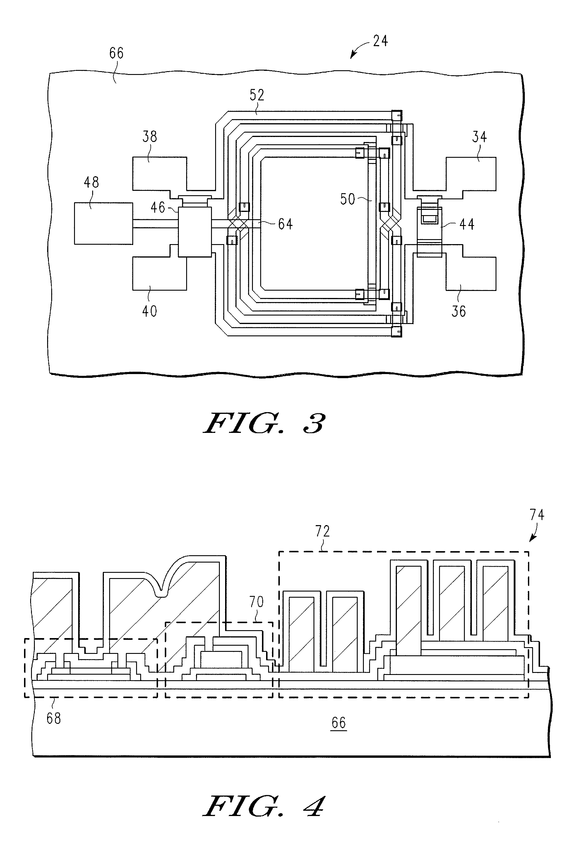
[0017]FIG. 1 to FIG. 9 illustrate an electronic assembly. The electronic assembly comprises a substrate, a balun transformer formed on the substrate and including a first winding and a second winding, each of the first and second windings having respective first and second ends, and a reaction circuit component formed on the substrate and electrically coupled to the second winding between the first and second ends thereof.

[0018]In one embodiment, the mid-point of the secondary winding of the balun transformer is connected to ground through reactive c...


PUM

PropertyMeasurementUnit
diameteraaaaaaaaaa
diameteraaaaaaaaaa
diameteraaaaaaaaaa

Abstract

An electronic assembly includes a substrate (66), a balun transformer (42) formed on the substrate (66) and including a first winding (50) and a second winding (52), each having respective first and second ends, and a reaction circuit component (48) formed on the substrate (66) and electrically coupled to the second winding (52) between the first and second ends thereof. The balun transformer (42) and the reaction circuit component (48) jointly form a harmonically suppressed balun transformer having a fundamental frequency, and the reaction circuit component (48) is tuned such that the harmonically suppressed balun transformer resonates at a selected harmonic of the fundamental frequency.

Description

FIELD OF THE INVENTION[0001]The present invention generally relates to an electronic assembly and a method for forming an electronic assembly, and more particularly relates to a balun transformer with improved harmonic suppression.BACKGROUND OF THE INVENTION[0002]In recent years, wireless communication devices, such as cellular phones, have continued to offer an ever increasing amount of features to users, along with improved performance and computing power, while the overall size of the devices has decreased. One important component found in such devices is a type of transformer referred to as a “balun.” Generally, baluns transform single-ended or “unbalanced” signals that are typically received and transmitted by antennas to differential or “balanced” signals that are typically found in the processing electronics of wireless communication devices.[0003]Two important parameters in the design of baluns are insertion loss and common mode rejection, as they determine the value selecti...

Claims


Application Information

Patent Timeline
Patent Type & Authority Patents(United States)
IPC IPC(8): H03H7/42H01P5/00
CPCH01F19/04H03H7/42Y10T29/4902H03H7/1775H03H2001/0064
Inventor LI, QIANGABROKWAH, JONATHAN K.HARTIN, OLIN L.LIU, LIANJUN
Owner NXP USA INC
Why Eureka
Try Eureka