Display device, viewing angle control device, and electronic apparatus

a technology of control device and display device, which is applied in the direction of color television details, television systems, instruments, etc., can solve the problem of preventing visibility heightening, and achieve the effect of simple arrangement and retain display quality

Active Publication Date: 2010-11-16
SHARP KK
View PDF70 Cites 54 Cited by
  • Summary
  • Abstract
  • Description
  • Claims
  • Application Information

AI Technical Summary

Benefits of technology

[0013]The present invention has been made in order to solve the foregoing problems, and it is an object of the present invention to realize a display device which has a simple arrangement, which retains display quality, and which makes it possible to switch to a mode in which a display image is hidden when the display is seen from a specific direction.
[0015]According to the foregoing arrangement, when the image displayed by the image display means is seen from an oblique direction in the multiple image display mode (narrow viewing angle mode), the switching image formed by the display switching means is superimposed on the image displayed by the image display means. This brings about such a visibility prevention effect that the image displayed by the image display means is prevented from being seen. Moreover, the switching image is an image that includes a transmission region and a non-transmission region, and the transmission region has an area smaller than 50% of that of the entire display screen (i.e., the non-transmission region has an area larger than 50% of that of the entire display screen. This further heightens the visibility prevention effect.
[0019]This makes it possible to realize an electronic apparatus which has a simple arrangement, which retains display quality, and which makes it possible to switch to a mode in which a display image is hidden when the display image is seen from a specific direction.

Problems solved by technology

This further heightens the visibility prevention effect.

Method used


Image

  • Display device, viewing angle control device, and electronic apparatus
  • Display device, viewing angle control device, and electronic apparatus
  • Display device, viewing angle control device, and electronic apparatus

Examples


example 1

Of THE ORIENTATION OF THE LIQUID CRYSTAL MOLECULES OF THE SW-LCD

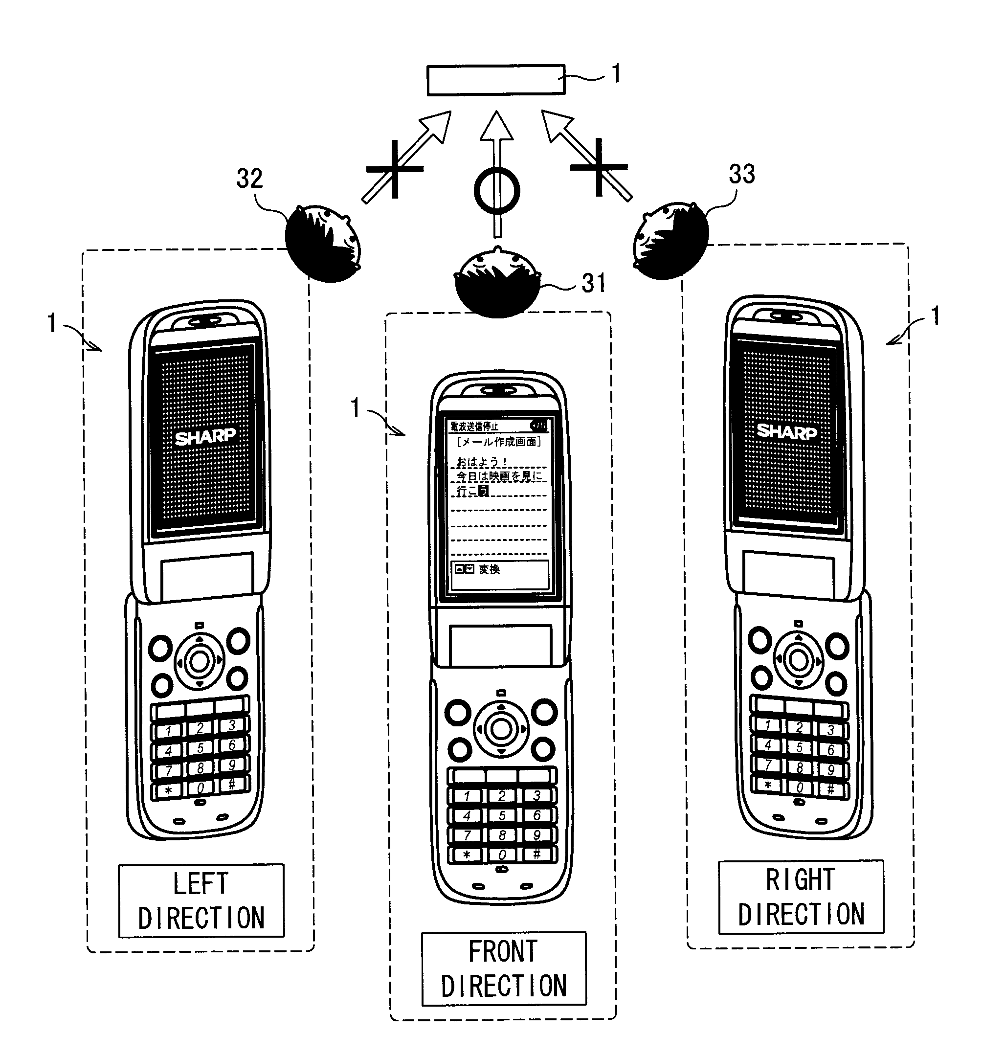
[0052]FIG. 5(a) shows a display surface of the display section 4 of the portable phone 1 so that the upper and lower sides of an image displayed by the main LCD 14 respectively correspond to the upper and lower sides of the page. Hereinafter, the right-and-left and up-and-down directions on the display screen are respectively referred to as “x direction” and “y direction”, and the direction of thickness of the display section 4 is referred to as “z direction”. Further, in FIGS. 5 through 11, the transparent electrode films 26 and 27 and the orienting films 24 and 25 are omitted.

[0053]First, as shown in FIG. 5(a), the second polarization plate 11 and the first polarization plate 13 are provided so as to have respective polarization transmission axes extending in the y direction. Further, the respective rubbing directions of the orienting films 24 and 25 are set to be parallel to the respective polarization transmission a...

example 2

Of THE ORIENTATION OF THE LIQUID CRYSTAL MOLECULES OF THE SW-LCD

[0064]Example 2 of the orientation of the liquid crystal molecules of the SW-LCD will be described with reference to FIG. 8. Example 2 of the orientation of the liquid crystal molecules is realized by using a SW-LCD 12′ obtained by replacing the orienting films 24 and 25 of the SW-LCD 12 with orienting films made of a vertical alignment polyimide material. With this, as shown in FIG. 8(a), the liquid crystal molecules can be oriented so as to be substantially perpendicular to the electrode substrates 21 and 22.

[0065]In this case, when no voltage is applied, the liquid crystal molecules of the SW-LCD 12′ are uniaxially oriented so as to be substantially perpendicular to the substrates 21 and 22. That is, when seen from the front direction, a liquid crystal molecule 37 looks like a perfect circle (When the projection drawing looks like a perfect circle, it is assumed that any direction is a long axis direction). Moreover,...

example 3

OF THE ORIENTATION OF THE LIQUID CRYSTAL MOLECULES OF THE SW-LCD

[0068]FIG. 9(a) shows the display section 4 of the portable phone 1 so that the upper and lower sides of the display screen respectively correspond to the upper and lower sides of the page.

[0069]First, as shown in FIG. 9(a), the second polarization plate 11 and the first polarization plate 13 are provided so as to have respective polarization transmission axes extending in the x direction. Further, the respective rubbing directions of the orienting films 24 and 25 are set to be perpendicular (y direction) to the respective polarization transmission axes of the first and second polarization plates 13 and 11 so as to be reversed 180° with respect to each other. That is, the orienting films 24 and 25 are oriented in such directions as to form an antiparallel structure. Moreover, the orienting films 24 and 25 are made of a horizontal alignment polyimide material so that the liquid crystal molecules are so oriented as to be ...


PUM

PropertyMeasurementUnit
voltageaaaaaaaaaa
angleaaaaaaaaaa
angleaaaaaaaaaa

Abstract

A portable phone has a main LCD and a SW-LCD, provided on a path of light to be transmitted by the main LCD, which electrically switches between (i) an image to be seen in a single image display mode and (ii) an image to be seen in a multiple image display mode. In the multiple image display mode, the display switch makes it possible that (a) the image displayed by the image display is seen from a front direction and (b) an image obtained by superimposing, onto the image displayed by the image display, a switching image formed by the display switch is seen from an oblique direction. The switching image is formed by providing, with at least one of a pair of transparent electrode films for applying a voltage to a liquid crystal layer, a patterning having an area larger than 50% of an area of a display screen.

Description

BACKGROUND OF THE INVENTION[0001]1. Field of the Invention[0002]The present invention relates to a display device and a viewing angle control device. Particularly, the present invention relates to a display device and a viewing angle control device each of which makes it possible to switch to a mode in which an image to be seen is changed in accordance with a viewing direction.[0003]2. Description of the Related Art[0004]In recent years, electronic apparatuses have become lighter and lighter, so that an electronic apparatus, such as a portable phone or a mobile personal computer, which has a display can be taken out to and used in a public place. This has caused such a problem that a confidential document or information that a user wishes to individually browse is seen by a person near the user.[0005]In response to this problem, there has been proposed a display device which can be set in a wide viewing angle display mode under normal conditions and which can be switched to a narrow...

Claims


Application Information

Patent Timeline
Patent Type & Authority Patents(United States)
IPC IPC(8): G09G3/36G02F1/1343
CPCG02F1/1323G02F1/13471G02F1/13G02F1/1335G02F1/1343
Inventor TAKATANI, TOMOOYABUTA, KOJIFUKUSHIMA, HIROSHI
Owner SHARP KK
Why Eureka
Try Eureka