Endoscopy device supporting multiple input devices

a multi-input, endoscope technology, applied in the field of remote-head imaging, can solve the problems of limited use of the camera control unit for video-endoscopes and remote-head imaging systems, and the inability to control the stereoscopic imaging head

Active Publication Date: 2010-12-21
GYRUS ACMI INC (D B A OLYMPUS SURGICAL TECH AMERICA)
View PDF75 Cites 40 Cited by
  • Summary
  • Abstract
  • Description
  • Claims
  • Application Information

AI Technical Summary

Benefits of technology

[0009]In accordance with another aspect of the present invention, the camera control unit includes a reconfigurable controller for timing and control of the sensor head, for receiving camera data from the sensor head, and for directing the camera data along a data path. A digital signal processor performs an image processing operation on camera data on the data path. The reconfigurable controller may be constructed from a hardware device with programmable functionality, such as a FPGA. The camera control unit also includes persistent re-writeable memory for storing program instructions or code executable by the digital signal processor to perform the image processing operation, and configuration information for configuring the reconfigurable controller to perform the timing and control, and otherwise to change the functionality of the camera control unit. The camera control unit further includes a system controller for loading the program instructions into the digital signal processor and for configuring the reconfigurable controller in accordance with the configuration information. By utilizing a persistent re-writeable memory for storing program instructions for the digital signal processor and configuration information for the reconfigurable controller, the present invention allows for updating functionality of the camera control unit in the field.
[0010]According to another aspect of the present invention, the camera control unit includes a reconfigurable controller for timing and control of the sensor head, for receiving camera data from the sensor head, and for performing a pixel preprocessing operation on the received camera data. The camera control unit further includes a digital signal processor for performing an image processing operation on the received camera data. In addition, the camera control unit includes a persistent re-writeable memory for storing multiple sets of program instructions executable by the digital signal processor to perform an image processing operation, and for storing multiple sets of configuration information for configuring the reconfigurable controller to perform the timing and control and pixel preprocessing operation. An input device allows for the selection of a set of program instructions to be used by the digital signal processor and selection of the configuration information for the reconfigurable controller. The camera control unit also includes a system controller for loading the selected set of program instructions into the digital signal processor and for reconfiguring the reconfigurable controller in accordance with the selected configuration information. In this way, a user can select specific processing operations and hardware configurations to be performed by the camera control unit.
[0012]According to another aspect of the present invention, the camera control unit includes a hardware clock for generating a clock signal, a digital signal processor (DSP) for receiving the hardware clock signal and for generating a DSP clock signal from the hardware clock signal, and a reconfigurable controller that receives sensor data based on a first clock signal and that outputs processed video data based on a second clock signal. The reconfigurable controller includes a reconfigurable logic array that receives the DSP clock signal and generates the first and second clock signals. In addition, a system controller is provided which reconfigures the logic array to generate selectably different first and second clock signals. In this way, input and output clock signals can be independently generated and adjusted from the same hardware clock signal.

Problems solved by technology

Conventional camera control units for video-endoscopes and remote-head imaging systems are limited in use, however, as they only support one type of input device.
For example, a conventional camera control unit for a flexible scope with a distal-end camera would be unable to control a stereoscopic imaging head.

Method used


Image

  • Endoscopy device supporting multiple input devices
  • Endoscopy device supporting multiple input devices
  • Endoscopy device supporting multiple input devices

Examples


Embodiment Construction

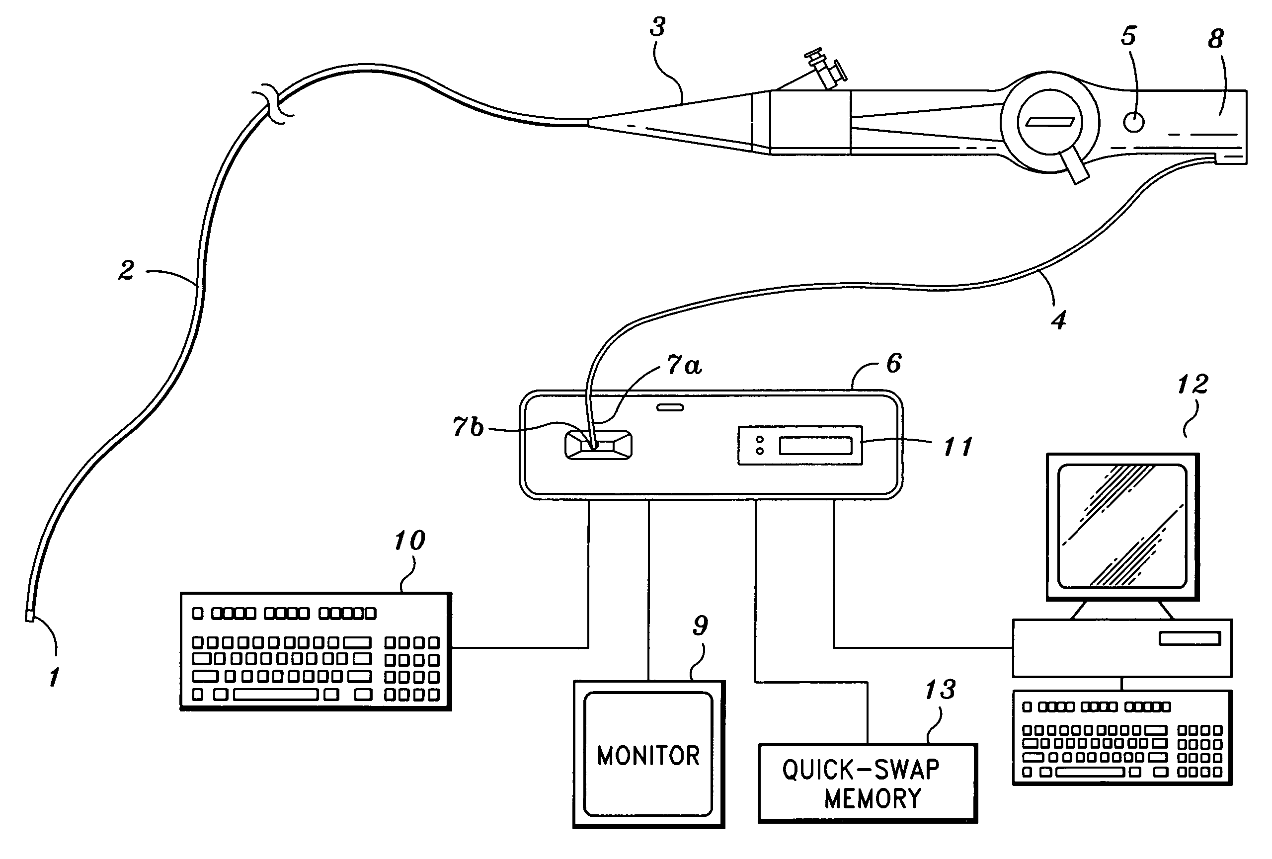
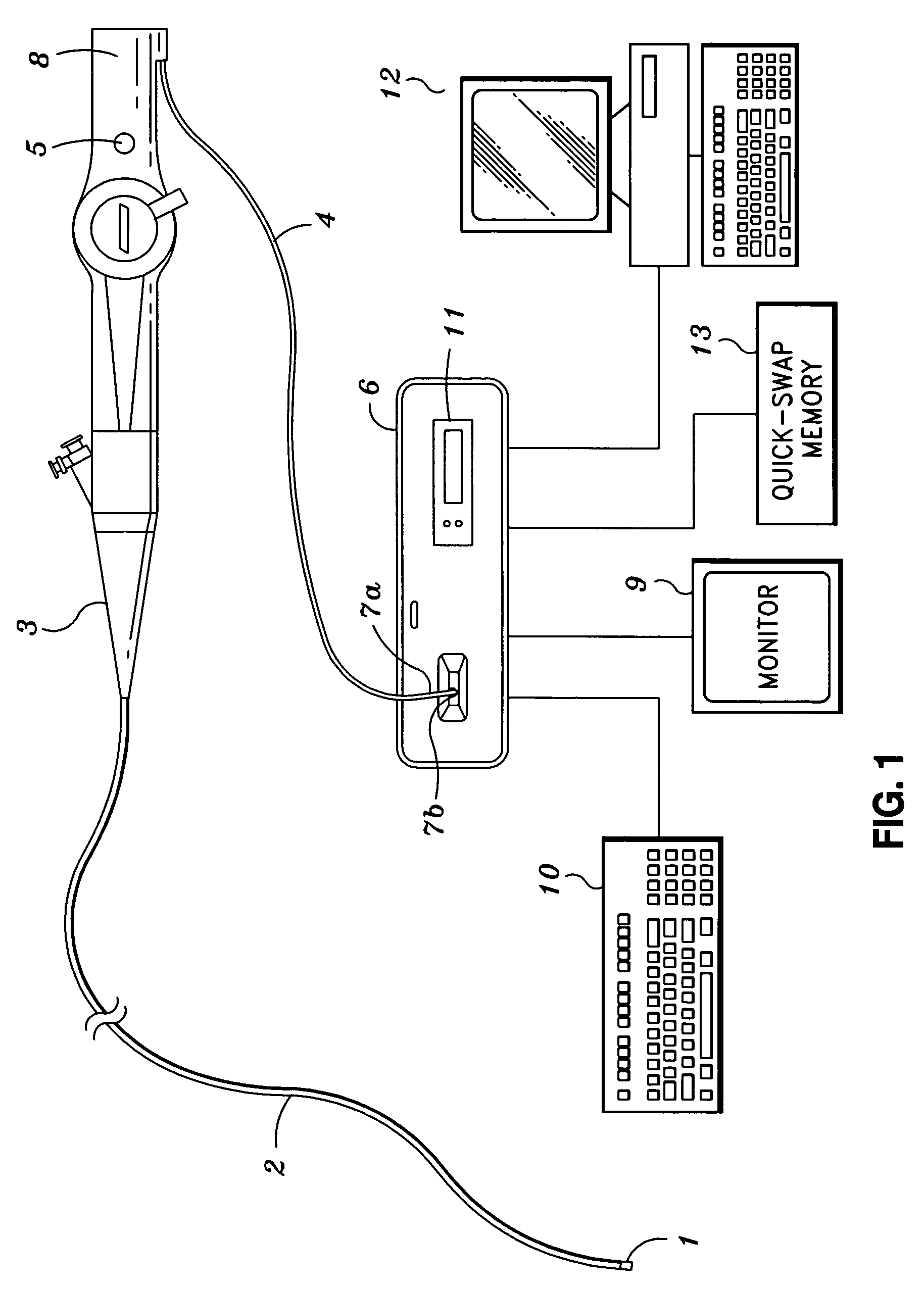
[0029]Referring now to the drawings, FIG. 1 depicts one possible configuration of the present invention. Camera control unit 6 is connected to flexible video endoscope 8 as well as monitor 9, keyboard 10, PC 12 and quick-swap memory device 13. In general, image data is captured by an image sensor located in distal tip 1 of endoscope 8 and is supplied to camera control unit 6 through umbilicus 4. Camera control unit 6 processes the image data, and formats the processed data to be output to monitor 9. User inputs to camera control unit 6 are achieved through keyboard 10, user interface 11, or PC 12. User interface 11 could include, but is not limited to, status LED's, switches, tactile buttons and LCD screens.

[0030]Flexible video endoscope 8 is connected to camera control unit 6 by attaching electrical connector 7A of umbilicus 4 to complementary connector 7B of camera control unit 6, which might be a card edge receptacle. Flexible video endoscope 8 includes distal tip 1, endoscope sh...


PUM


Abstract

The present invention provides a remote-head imaging system with a camera control unit capable of supporting multiple input devices. The camera control unit detects an input device to which it is connected and changes the camera control unit's internal functionality accordingly. Such changes includes altering clock timing, changing video output parameters, and changing image processing software. In addition, a user is able to select different sets of software program instructions and hardware configuration information based on the head that is attached. The remote-head imaging system utilizes field-programmable circuitry, such as field-programmable gate arrays (FPGA), in order to facilitate the change in configuration.

Description

BACKGROUND AND SUMMARY[0001]1. Field of the Invention[0002]The present invention generally relates to remote-head imaging, and more particularly, to an endoscopy device with a multi-purpose camera control unit that supports multiple input devices.[0003]2. Description of the Related Art[0004]Remote-head imaging devices, and more particularly, endoscopes and video-endoscopes, are used in medical and industrial applications to view inside of cavities, bodily canals, hollow organs, and other remote locations. Typically, video-endoscopes consist of an input device, such as a distal-end (the end closest to the patient) camera on a rigid or flexible scope, that is attached to a camera control unit. The camera control unit typically supplies power to the camera, controls operation of the camera, receives raw video and non-video data from the camera, and outputs processed video data to a video display.[0005]Conventional camera control units for video-endoscopes and remote-head imaging system...

Claims


Application Information

Patent Timeline
Patent Type & Authority Patents(United States)
IPC IPC(8): H04N9/47A61B1/04A62B1/04H04N5/232H04N7/18
CPCA61B1/045A61B1/0676A61B1/0684H04N5/23209H04N2005/2255H04N23/555H04N23/663
Inventor ADLER, DORONFINKMAN, SHAIBLUMZVIG, ARIE
Owner GYRUS ACMI INC (D B A OLYMPUS SURGICAL TECH AMERICA)
Why Eureka
Try Eureka