Camera slider system

a slider and camera technology, applied in the field of camera slider systems, can solve the problems of affecting the smooth and continuous motion of the camera, requiring expensive and awkward transportation equipment, and the known dolly construction is generally quite large, and achieves the effect of stable configuration for supporting the camera

Inactive Publication Date: 2011-02-22
WOOD DENNIS
View PDF10 Cites 13 Cited by
  • Summary
  • Abstract
  • Description
  • Claims
  • Application Information

AI Technical Summary

Benefits of technology

[0010]By providing a linkage which pivotally couples the camera mount to a carriage assembly on the elongate support members, the orientation of the camera relative to the elongate supports is very flexible for accommodating different elevations and orientations using a small compact configuration of parts. Furthermore by providing a linkage comprising a pair of link members at opposing ends of the camera mount, a very stable configuration for supporting the camera is provided. Furthermore, the use of rollers ensures a smooth movement of the camera along the elongate support members so that there are no undesired jerking movements in the resulting captured image.

Problems solved by technology

Known dolly constructions however generally are quite large requiring equipment that is expensive and awkward to transport to support the camera for rolling movement along the tracks.
The sliding configuration of the blocks can interfere with the desired smooth and continuous motion of the camera.
Furthermore the direct mounting of the plate on the slider blocks limits the adjustability of the camera positioning so that a limited number of different types of shots are available.

Method used


Image

  • Camera slider system
  • Camera slider system
  • Camera slider system

Examples


first embodiment

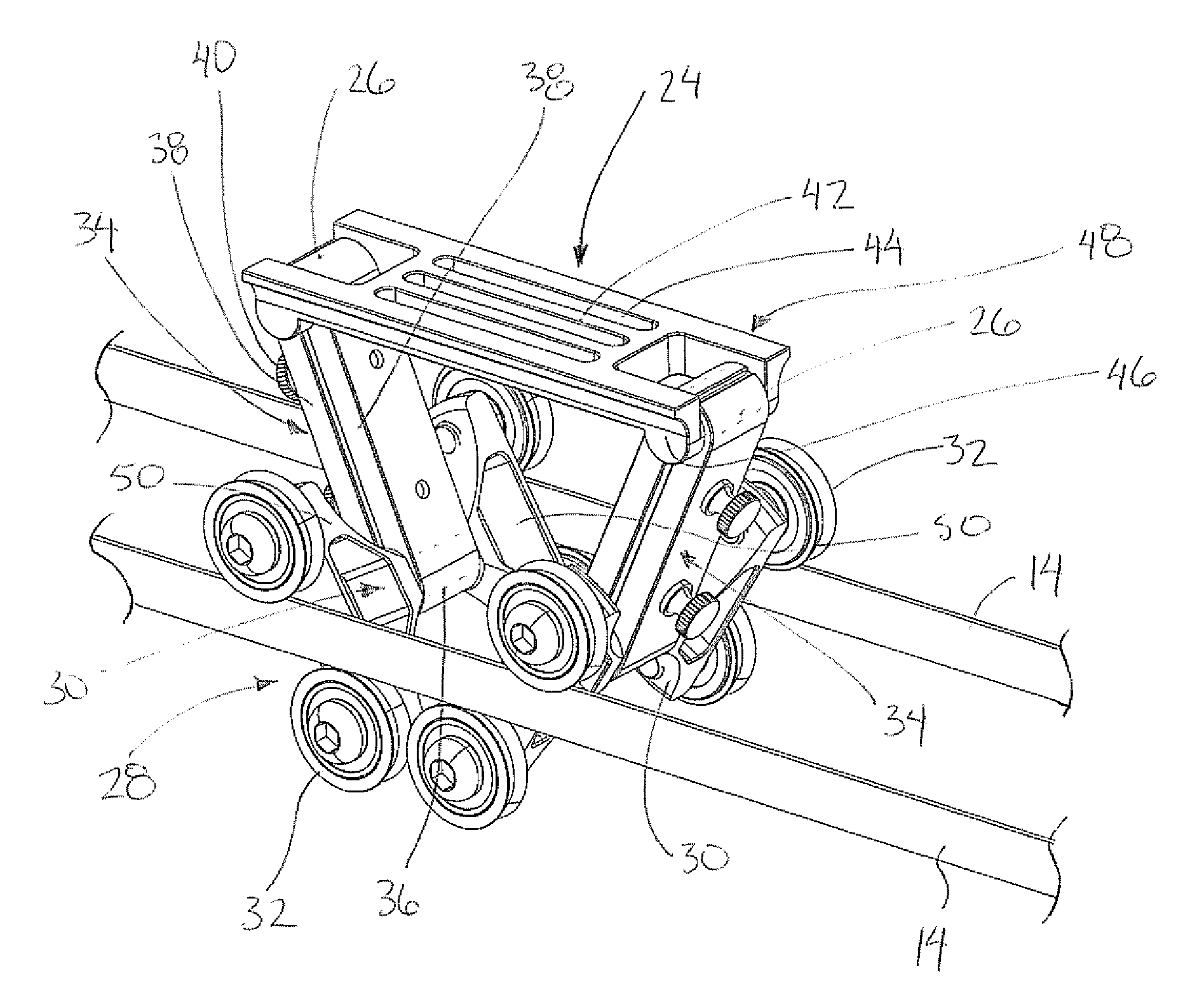
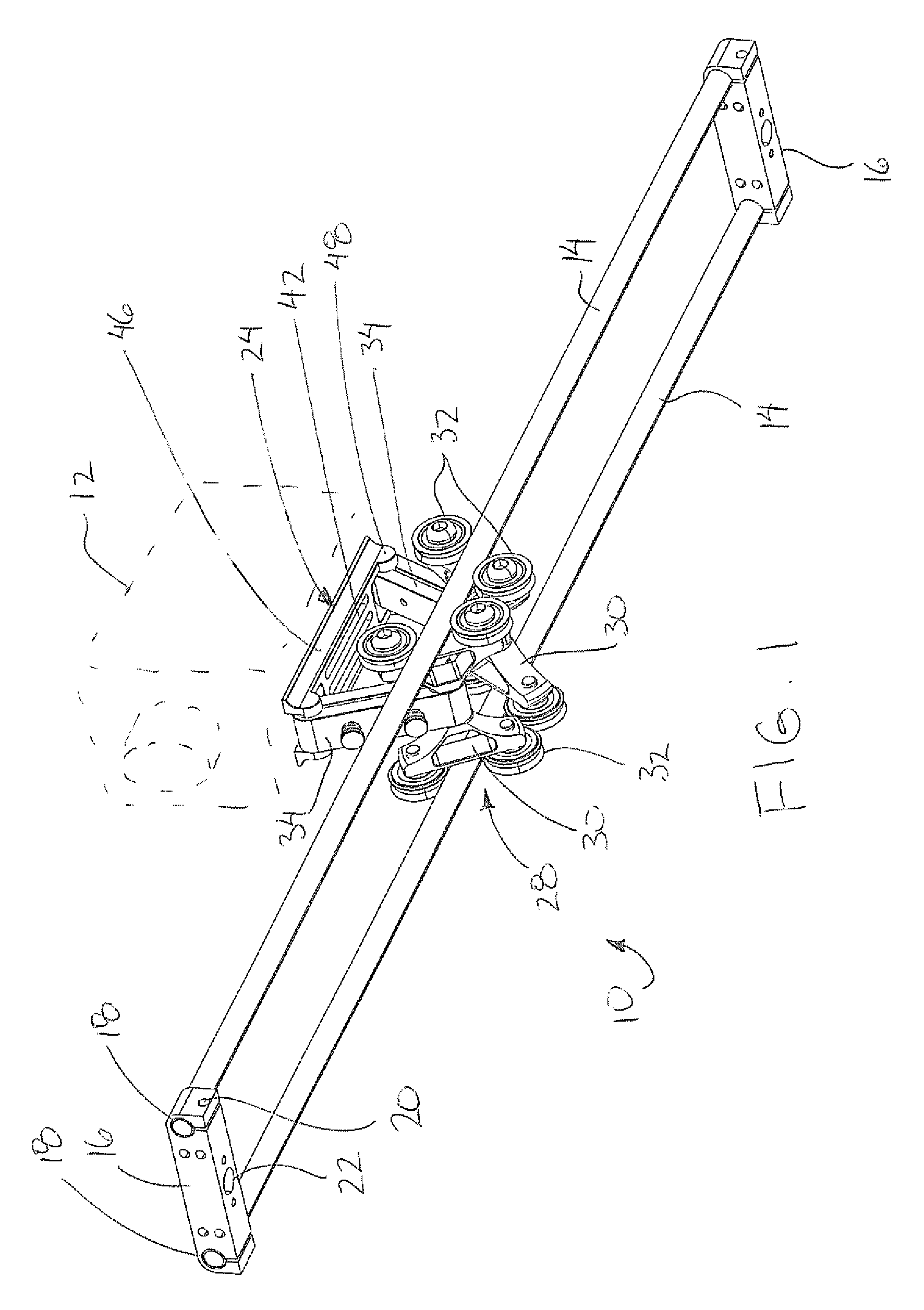
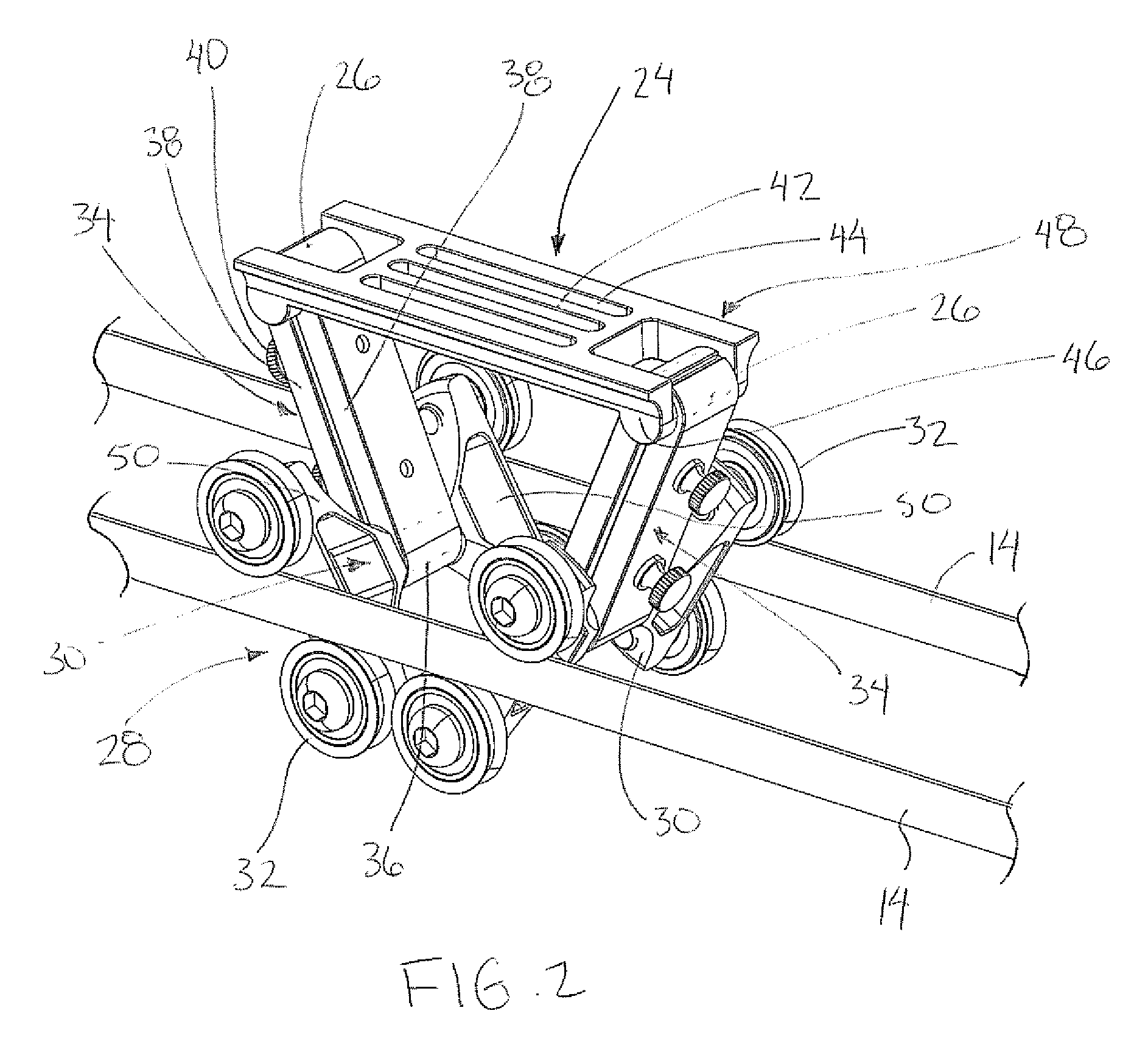
[0058]Turning now more particularly to the camera slider system shown in FIGS. 1 through 5, the camera mount 24 in this instance comprises a plate member having a central portion 42 which comprises a flat upper surface locating a plurality of longitudinally extending slots 44 therein. The slots 44 are parallel and spaced relative to one another in the lateral direction such that each slot extends substantially the full length of the central portion 42 in the longitudinal direction. The slots extend fully through from the top side to the bottom side of the central portion of the camera mount for receiving suitable fasteners therein which permit the body of the camera to be coupled directly thereto. The camera mount further comprises depending side flanges 46 which extend downwardly from respective side edges of the plate member such that the side flanges are parallel and spaced apart from one another to extend in the longitudinal direction. The two side flanges both extend outward in...

second embodiment

[0064]Turning now to the second embodiment shown in FIGS. 6 through 12, the carriage body may instead comprise a single carriage body 30 which supports the two pivot shafts 36 thereon at opposing ends at a fixed spacing which is greater than the spacing in the longitudinal direction between the pivot shafts 26 located at a fixed spacing on the camera mount 24.

[0065]The camera mount 24 in this instance comprises a central bowl portion 54 which tapers downwardly and inwardly from an upper rim to a lower central opening. The bowl portion 54 is suitably shaped for mounting a commercially available tripod head of the type having a convex bottom portion with a central stud onto which a clamp fastener 56 can be threadably secured. In this manner a portion of the bowl portion 54 of the camera mount is clamped between the clamp fastener 56 and the convex bottom of the tripod head so that the tripod head can be fixed onto the camera mount at various orientations therebetween. The tripod head ...


PUM


Abstract

The camera slider system supports a camera for longitudinal sliding or rolling movement along a pair of elongate support members which are parallel and spaced apart from one another. The camera mount supporting the camera thereon is supported by a pair of link members pivotally coupled between opposing ends of the camera mount and a carriage assembly which is movable along the rails. The orientation of the camera relative to the elongate supports is readily adjustable by adjusting the pivotal link members while the camera remains supported in a very stable configuration. Rollers or bearings ensure a smooth movement of the camera along the elongate support members so that there are no undesired jerking movements in the resulting captured image.

Description

[0001]This application is a Continuation-in-part of U.S. patent application Ser. No. 12 / 246,548, filed Oct. 7, 2008 now U.S. Pat. No. 7,854,556 and claims foreign priority benefits from Canadian Patent Application No. 2,641,010 filed Oct. 7, 2008 and Canadian Patent Application No. 2,687,177 filed May 12, 2009.FIELD OF THE INVENTION[0002]The present invention relates to a camera slider system comprising a camera mount arranged to support a video camera thereon for movement with the camera mount along a pair of elongate support members, and more particularly relates to a camera slider system in which the camera mount is adjustable relative to a carriage assembly supported for movement along the elongate support members.BACKGROUND[0003]When filming with a video camera, a common method of capturing video involves displacing the camera along a track using a dolly. Known dolly constructions however generally are quite large requiring equipment that is expensive and awkward to transport t...

Claims


Application Information

Patent Timeline
Patent Type & Authority Patents(United States)
IPC IPC(8): G03B17/00
CPCG03B17/561F16M11/425F16M2200/08
Inventor WOOD, DENNIS
Owner WOOD DENNIS
Why Eureka
Try Eureka