Intramedullary nail and implant system comprising the nail

a technology which is applied in the field of intramedullary nail and implant system comprising the nail, can solve the problems of implant brakeage when it is overloaded, the smallest cross sectional area of the proximal portion of the conventional intramedullary nail, and the implant breakage. it can facilitate the healing of femur fracture and achieve stable configuration of both the implant system and the fractur

Active Publication Date: 2015-07-07
STRYKER EURO OPERATIONS HLDG LLC
View PDF35 Cites 15 Cited by
  • Summary
  • Abstract
  • Description
  • Claims
  • Application Information

AI Technical Summary

Benefits of technology

[0010]Aspects of the present disclosure are directed to the provision of an intramedullary nail and an implant system that facilitate a rapid healing of a femur fracture and results in a stable configuration of both the implant system and the fracture.

Problems solved by technology

It has been found that non-unions of peri and intratrochanteric fractures as well as sub-trochanteric fractures treated with an intramedullary nail can lead to overloading and thus breakage of the implant.
Specifically, conventional intramedullary nails may be damaged at their smallest cross sectional area of the proximal portion, i.e., in the area of the transverse bore, for example during drilling with a lag screw step drill.
Such a damage may lead to a weakening of the intramedullary nail in a critical area and result in brakeage of the implant when it is overloaded, (e.g., by the patient's weight).
Moreover, the stability between the intramedullary nail and the femoral lag screw is decreased in such a situation and the implant system may fail to hold the fracture in a stable configuration, such that a well-defined compressive sliding of the femoral lag screw can no longer be guaranteed.

Method used


Image

  • Intramedullary nail and implant system comprising the nail
  • Intramedullary nail and implant system comprising the nail
  • Intramedullary nail and implant system comprising the nail

Examples


Embodiment Construction

[0030]In the following description of exemplary embodiments, the same or similar components will be denoted by identical reference numerals. It will be appreciated that while the following embodiments will primarily be described with respect to the treatment of a femur, the implant presented herein, with suitable modifications, could also be used for treatment of other bones.

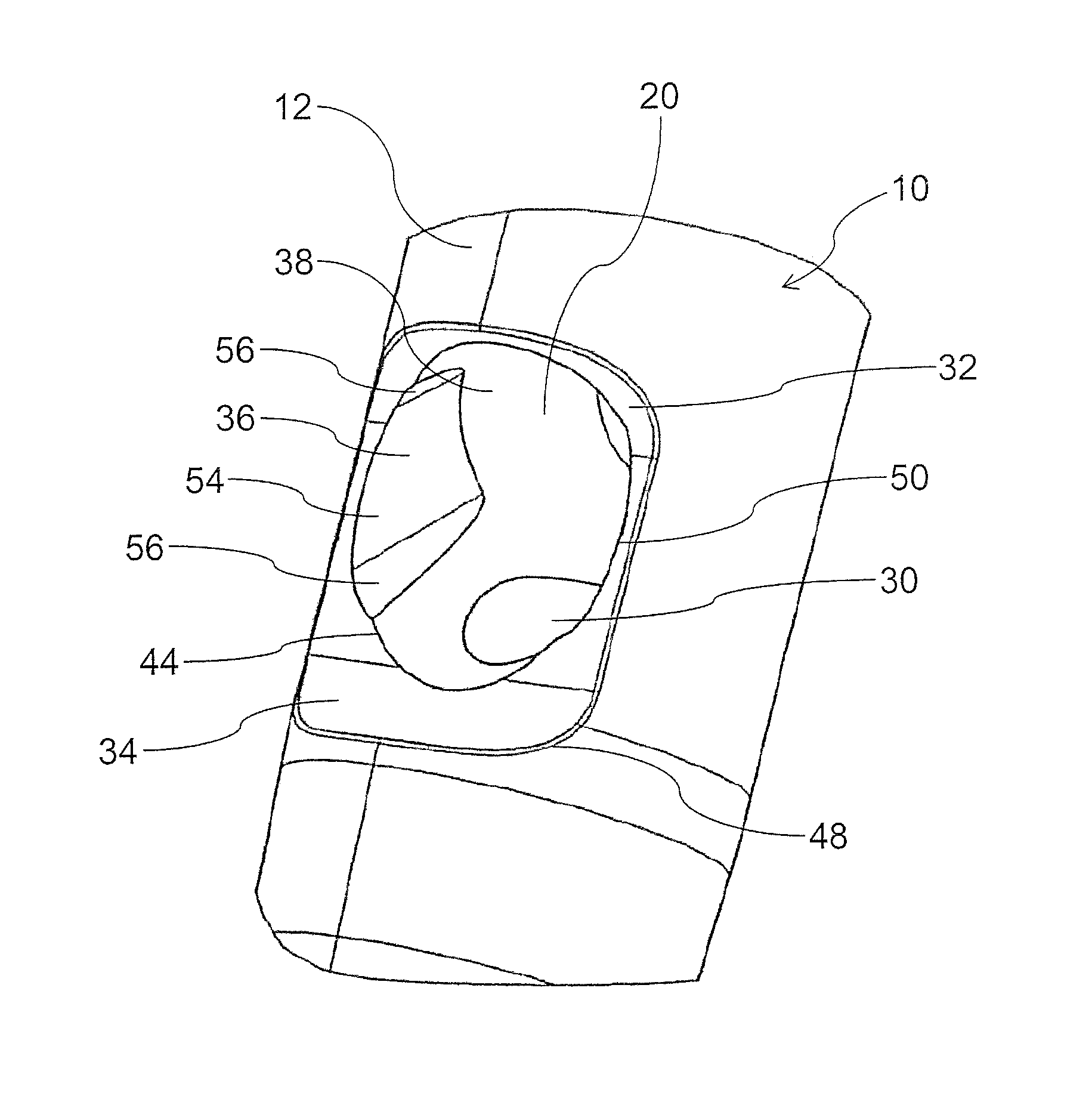
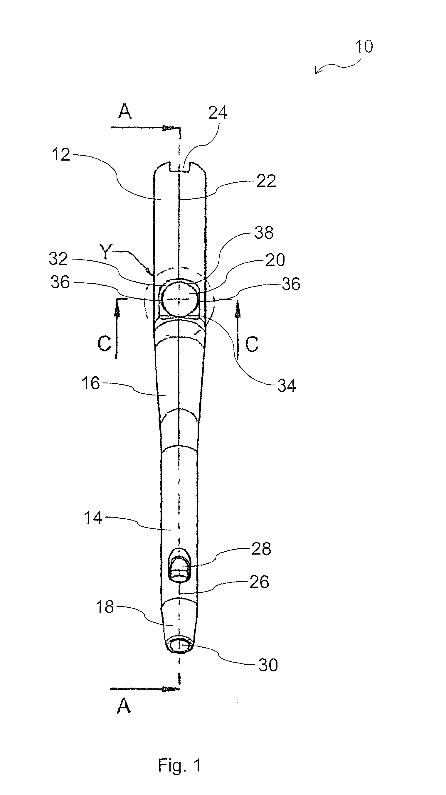
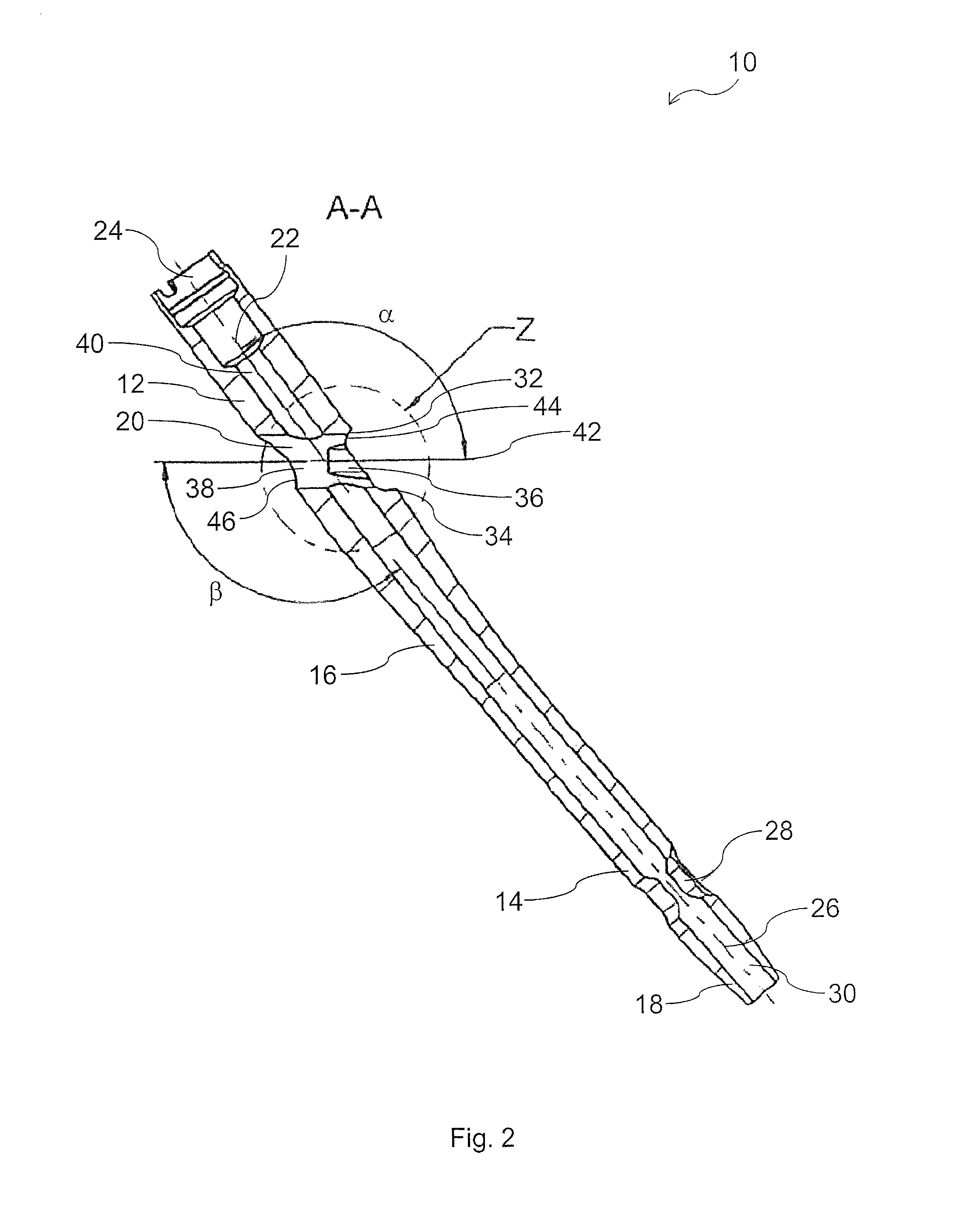
[0031]Referring to FIG. 1, there is shown a lateral side view of an embodiment of an intramedullary nail 10 for use in orthopaedic surgery for fixation of bone, such as a femur (not shown in FIG. 1). The intramedullary nail 10 is made of a biocompatible material such as stainless steel, titanium or a titanium alloy. The intramedullary nail 10 includes a rod-shaped body insertable into the inner cavity of a bone (marrow cavity), e.g., into the intramedullary canal of a femur.

[0032]The intramedullary nail 10 includes a proximal portion 12, a distal portion 14 and an intermediate portion 16 therebetween. Thus, the ...


PUM

PropertyMeasurementUnit
angleaaaaaaaaaa
angleaaaaaaaaaa
widthaaaaaaaaaa

Abstract

An intramedullary nail has a posterior side, an anterior side, a proximal portion and a distal portion is described. A transverse bore is arranged in the proximal portion and is configured to receive a bone engagement member. The transverse bore includes at least two recesses formed at an inner wall of the transverse bore, wherein one recess is arranged on the posterior side and the other recess is arranged on the anterior side of the transverse bore of the intramedullary nail.

Description

CROSS-REFERENCE TO RELATED APPLICATIONS[0001]The present application claims priority from European Patent Application No. 12 006 837.4 filed Oct. 1, 2012, the disclosure of which is hereby incorporated herein by reference.BACKGROUND OF THE INVENTION[0002]The present disclosure generally relates to an intramedullary nail for internal fixation of a bone, such as a femur. The disclosure further relates to an implant system for use in orthopaedic surgery and to a method of manufacturing an intramedullary nail.[0003]Femur fractures commonly occur in the femoral neck and the trochanteric regions. Today, trochanteric and sub-trochanteric femur fractures are treated with an intramedullary nail having a transverse bore in a proximal portion to receive a femoral neck screw usually provided in the form of a lag screw. Such a nail is shown in U.S. Pat. Nos. 5,176,681 and 5,454,813, the disclosures of which are incorporated herein by reference.[0004]For fracture treatment the intramedullary nail...

Claims


Application Information

Patent Timeline
Patent Type & Authority Patents(United States)
IPC IPC(8): A61B17/72A61B17/76A61B17/74B23C3/28
CPCA61B17/7241A61B17/72A61B17/744B23C3/28Y10T409/303808A61B17/7233A61B17/74A61B17/88A61B2017/564A61B17/742A61B2017/00526
Inventor SIMON, BERNDKLUVER, HENDRIKPAULSEN, MARTJE
Owner STRYKER EURO OPERATIONS HLDG LLC
Why Eureka
Try Eureka