Induction heating apparatus

a technology of induction heating and heating apparatus, which is applied in the direction of induction heating, ohmic resistance heating, electric/magnetic/electromagnetic heating, etc., can solve the problems of increasing contact resistance, preventing the function of electrostatic shield, and performing sufficiently, so as to facilitate production and facilitate the effect of connection, stable configuration and low cos

Inactive Publication Date: 2005-12-15
PANASONIC CORP
View PDF9 Cites 12 Cited by
  • Summary
  • Abstract
  • Description
  • Claims
  • Application Information

AI Technical Summary

Benefits of technology

[0009] In order to solve the above-mentioned conventional problem, an induction heating apparatus in accordance with the present invention has a configuration wherein a stationary plate having electrical insulation is provided between a top plate and an induction heating coil, and the stationary plate is provided with an electrostatic shield and connection portions for connecting the electrostatic shield to a low-potential portion. Hence, production is facilitated and the influence of the high temperature of a matter to be heated on the electrostatic shield is relieved in comparison with the conventional method wherein the top plate is provided with the electrostatic shield. In addition, since, unlike the top plate, the stationary plate is not a component constituting the outer shell, it has freedom in the selection of shape and matter, and the connection between the electrostatic shield and the connection portions can have a stable configuration, whereby it is possible to ensure inexpensively connection with high reliability less susceptible to the influences of vibration of the apparatus, drop impact of the apparatus, etc.

Problems solved by technology

However, in the case of the above-mentioned conventional configuration, the strength of the connection between the electrode 4a and the lead wire or the stability and reliability of the connection are insufficient; for example, because of some reasons, such as the occurrence of a tension force during a production process, reduction in the strength of solder owing to the heat from the matter 3 to be heated during cooking and the vibration or drop impact of the apparatus, the lead wire may be disconnected from the electrode 4a, the spring terminal may be oxidized, the contact part between the electrostatic shield and the spring terminal is separated owing to vibration or the like, whereby there is a fear of causing a problem of increasing the contact resistance and preventing the function of the electrostatic shield 4 from performing sufficiently.

Method used


Image

  • Induction heating apparatus
  • Induction heating apparatus
  • Induction heating apparatus

Examples


embodiment 1

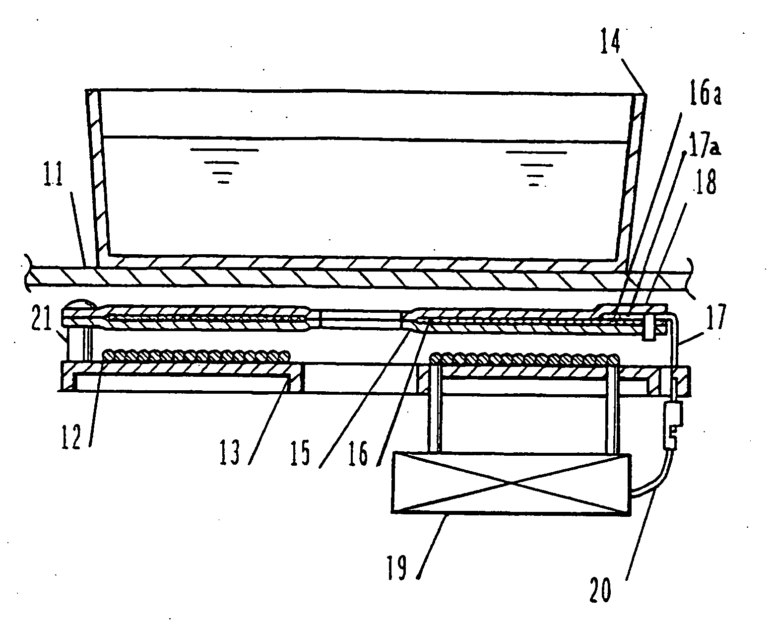
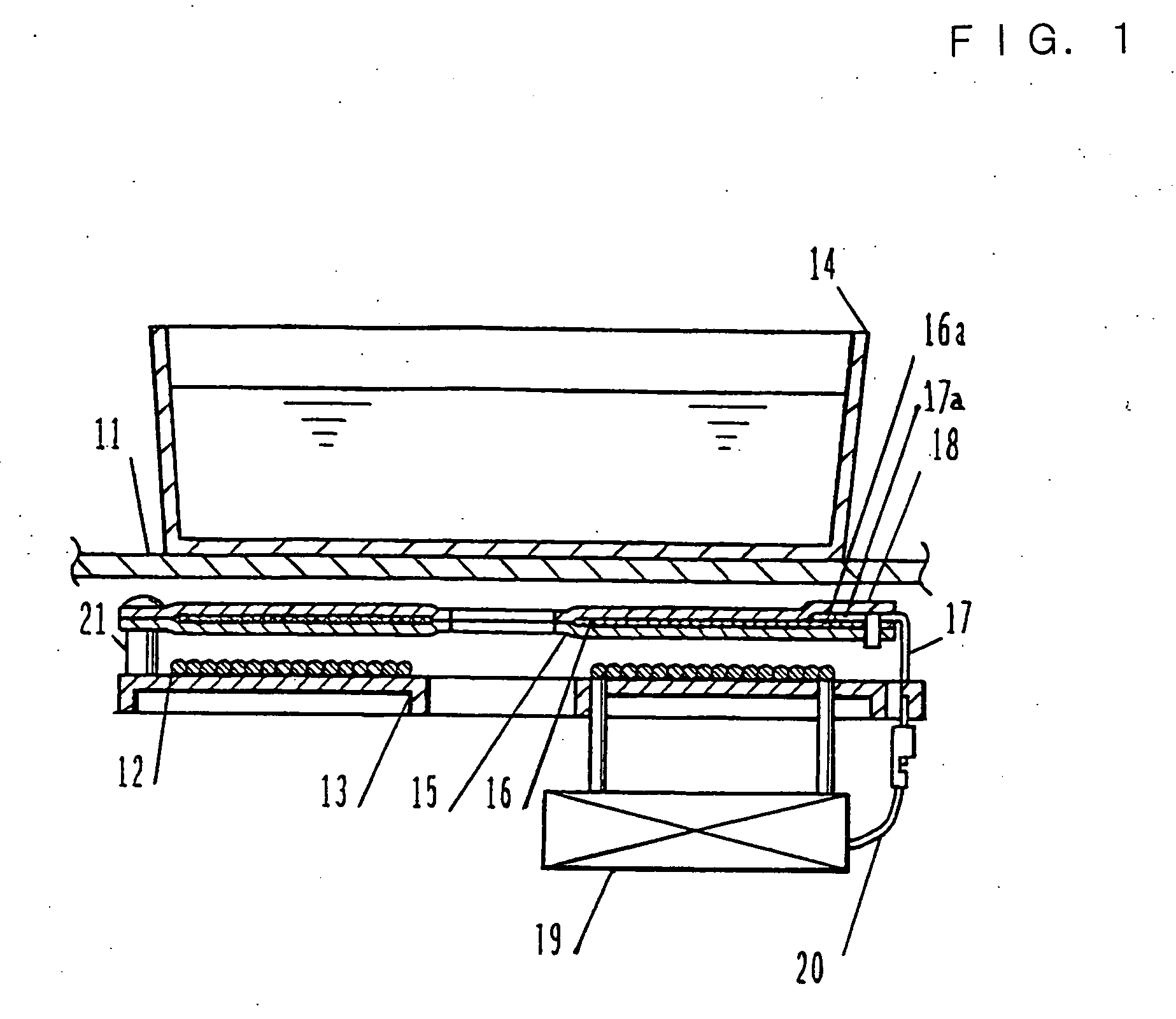
[0039] The general outline of an induction heating apparatus in accordance with Embodiment 1 of the present invention will be elucidated. In FIG. 1, numeral 11 designates a top plate provided in the upper portion of the main body (not shown) forming an outer shell, and numeral 12 designates an induction heating coil placed on an induction heating coil base 13. Numeral 14 designates a matter to be heated, such as a pan, which is heated by induction heating, and numeral 15 designates a stationary plate made of an inorganic insulator, such as mica. Numeral 16 designates an electrostatic shield made of a mixture of an adhesive and conductive paint containing carbon or the like and applied onto the stationary plate 15, the electrostatic shield comprising a conductive pattern which covers the entire area of the induction heating coil 12 so that the high voltage of the induction heating coil 12 is not induced in the matter 14 to be heated, and connection portions 16a provided at both ends ...

embodiment 2

[0081] The thermal expansion coefficient of the stationary plate 15 or the electrostatic shield 16 generally differs from the thermal expansion coefficient of the connection terminal 17. When the stationary plate 15 and / or the electrostatic shield 16 expand and contract repeatedly owing to temperature change during a long-term use, cracks may occur at the connection part between the electrostatic shield 16 and the connection terminal 17 or improper conduction may be caused at the connection portion, owing to mechanical stress. In Embodiment 2, the grommet 40 is used to secure the stationary plate 15, the electrostatic shield 16 and the connection terminal 17. Although the grommet 40 firmly secures the stationary plate 15 and the connection terminal 17 in the thickness direction of the stationary plate 15, slight sliding is allowed among the stationary plate 15, the electrostatic shield 16 and the connection terminal 17 in a direction parallel to the surface of the stationary plate 1...


PUM


Abstract

An induction heating apparatus wherein an electrostatic shield and the low-potential portion of an inverter circuit are electrically connected securely is provided. The induction heating apparatus in accordance with the present invention comprises a top plate 11 on which a matter 14 to be heated is placed, an induction heating coil 12 for induction heating the matter 14 to be heated, driving means 19 for driving the induction heating coil 12, and a stationary plate 15 and a cover for stationary plate 18 provided between the matter 14 to be heated and the induction heating coil 12, wherein connection portions 17a each integrated with a connection terminal 17 are electrically connected to the electrostatic shield 16 provided on the stationary plate 15 using a conductive adhesive, and the connection parts are held between the stationary plate 15 and the cover for stationary plate 18. With this configuration, the connection parts can be held securely and stably.

Description

TECHNICAL FIELD [0001] The present invention relates to an induction heating apparatus provided with an electrostatic shield between a matter to be heated and an induction heating coil. BACKGROUND ART [0002] Conventionally, as this kind of induction heating apparatus, for example, the apparatus described in Japanese Laid-open Patent Application No. Sho 61-16491 was available. FIG. 9 is a view showing the equivalent circuit of the induction heating coil and its peripheral portion in this kind of conventional induction heating apparatus. [0003] The configuration of the conventional induction heating apparatus will be elucidated below using FIG. 9. In FIG. 9, numeral 1 designates a top plate; an induction heating coil 2 is provided below the top plate 1; and a matter 3 to be heated is placed thereon. Numeral 4 designates an electrostatic shield applied to the bottom face of the top plate 1 and electrically connected to the low-potential portion of an inverter circuit (not shown) for dr...

Claims


Application Information

Patent Timeline
Patent Type & Authority Applications(United States)
IPC IPC(8): H05B6/12
CPCH05B6/1209H05B2206/022H05B6/12
Inventor KATAOKA, AKIRAHIROTA, IZUOAIHARA, KATSUYUKIMAKIO, NOBUYOSHI
Owner PANASONIC CORP
Why Eureka
Try Eureka