Parallel ink jet printing device and relative manufacturing

a technology of ink jet printing and printing head, which is applied in the direction of printing and inking apparatus, etc., can solve the problems of faulty device, inability to operate multiple nozzles and/or heating elements, and difficulty in parallel or serial parallel printing devices, etc., and achieve the effect of low production time and cos

Inactive Publication Date: 2011-07-26
TELECOM ITALIA SPA +1
View PDF21 Cites 5 Cited by
  • Summary
  • Abstract
  • Description
  • Claims
  • Application Information

AI Technical Summary

Benefits of technology

The main object of this invention consists in producing ink jet printing devices having parallel or serial-parallel type heads, without the drawbacks mentioned above and which can be made with low production times and costs.
Yet another object of the invention is that of providing an ink jet printing device with nozzles arranged in a line in a direction parallel to the printing axis, of low dimensions and cost and which guarantees a good printing resolution.
A further object of the invention is to produce a colour ink jet printing device, with parallel or serial-parallel heads of compact dimensions and at low cost. These objects are achieved by the parallel or serial-parallel printing device of the invention according to the characteristic parts of the main claims.

Problems solved by technology

The manufacture of ink jet printing devices having parallel or serial-parallel heads conflicts however with the difficulty of making, with a yield sufficient to allow components to be obtained economically, chips of considerable length (>1 inch) that have zero defects.
Furthermore, there is also the risk, at the conclusion of the manufacturing process, of ending up with a faulty device for the sole fact that, in a head, one only of the numerous nozzles and / or heating elements is not functioning.
The scale of these problems has been such as to render the production of these devices economically very unattractive up till now.
However, other problems arise from using this structure such as, for instance, that of the impossibility of using modules in which feeding of the ink occurs through common slots.
This, however, gives rise to a worsening of the alignment of the dots in the printing phase and a more complex logic for controlling activation of the nozzles and in the associated circuitry.

Method used


Image

  • Parallel ink jet printing device and relative manufacturing
  • Parallel ink jet printing device and relative manufacturing
  • Parallel ink jet printing device and relative manufacturing

Examples


Embodiment Construction

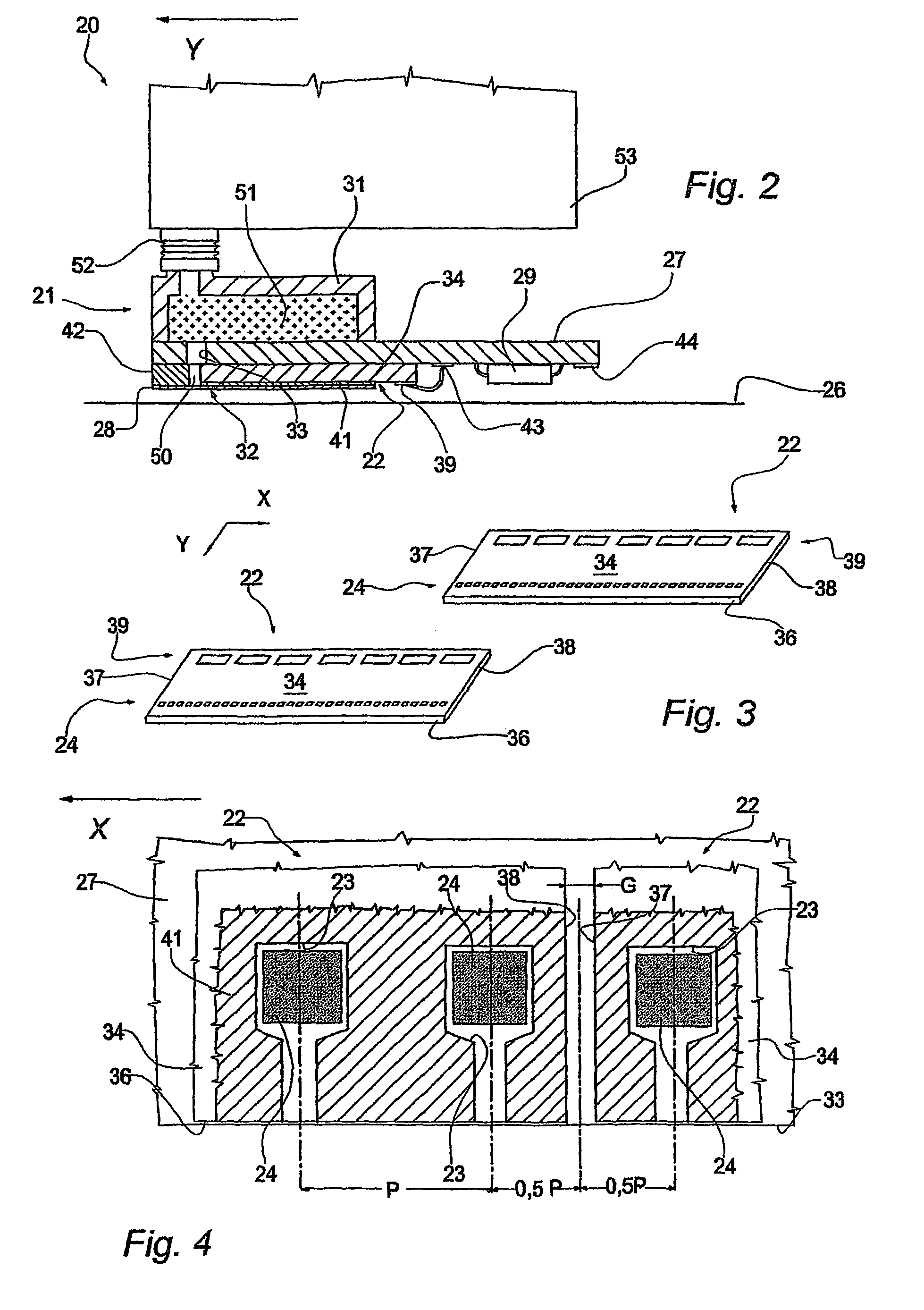
As regards the technology selected to produce the modules of the heads, the invention relies on known techniques. The relative details will not therefore be discussed comprehensively also because they are of no importance, in themselves, for the purpose of understanding of the invention. Against this backdrop, the representations of the drawings have been schematized, and illustration of the elements of the invention has been given priority over those of details that are already known.

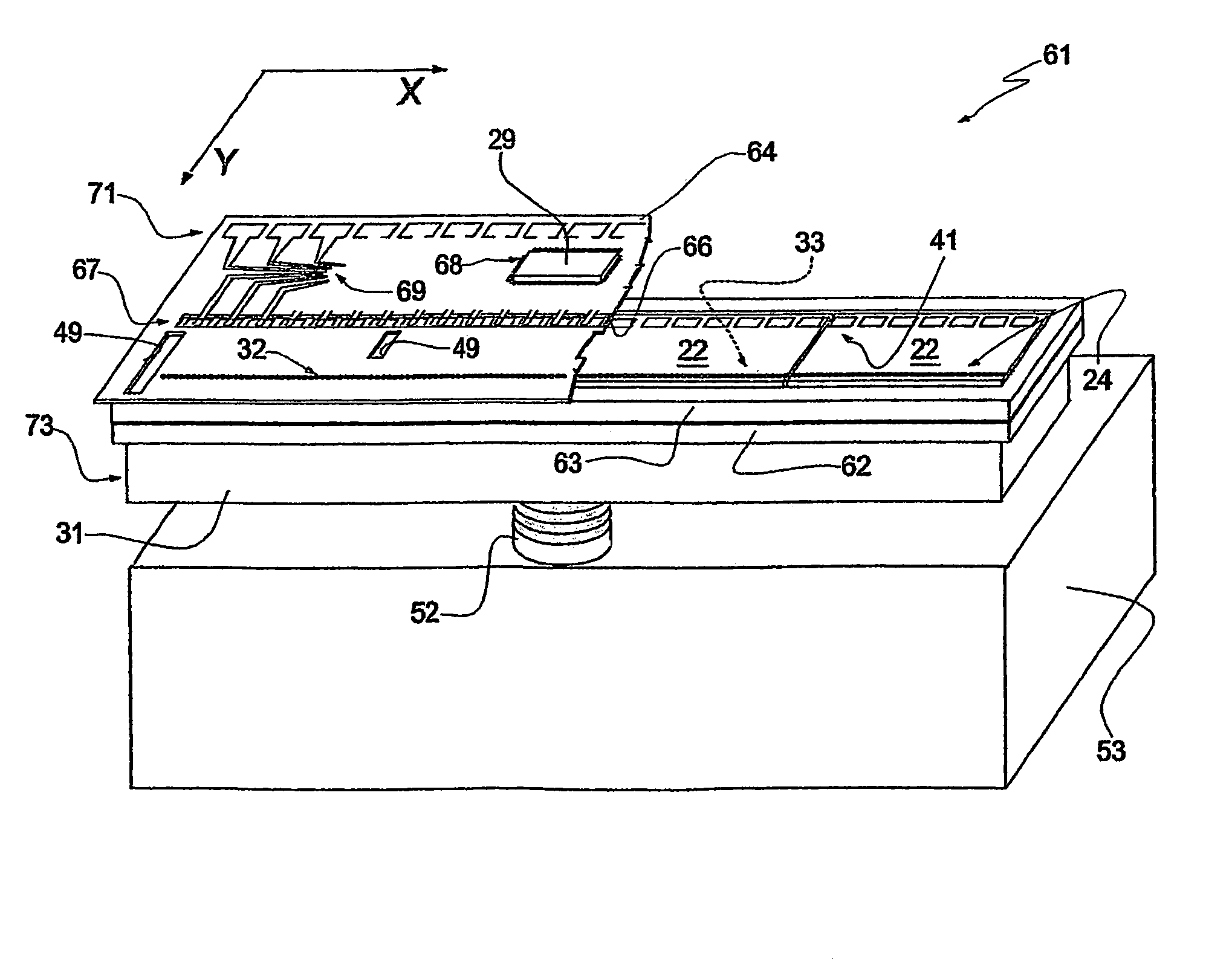
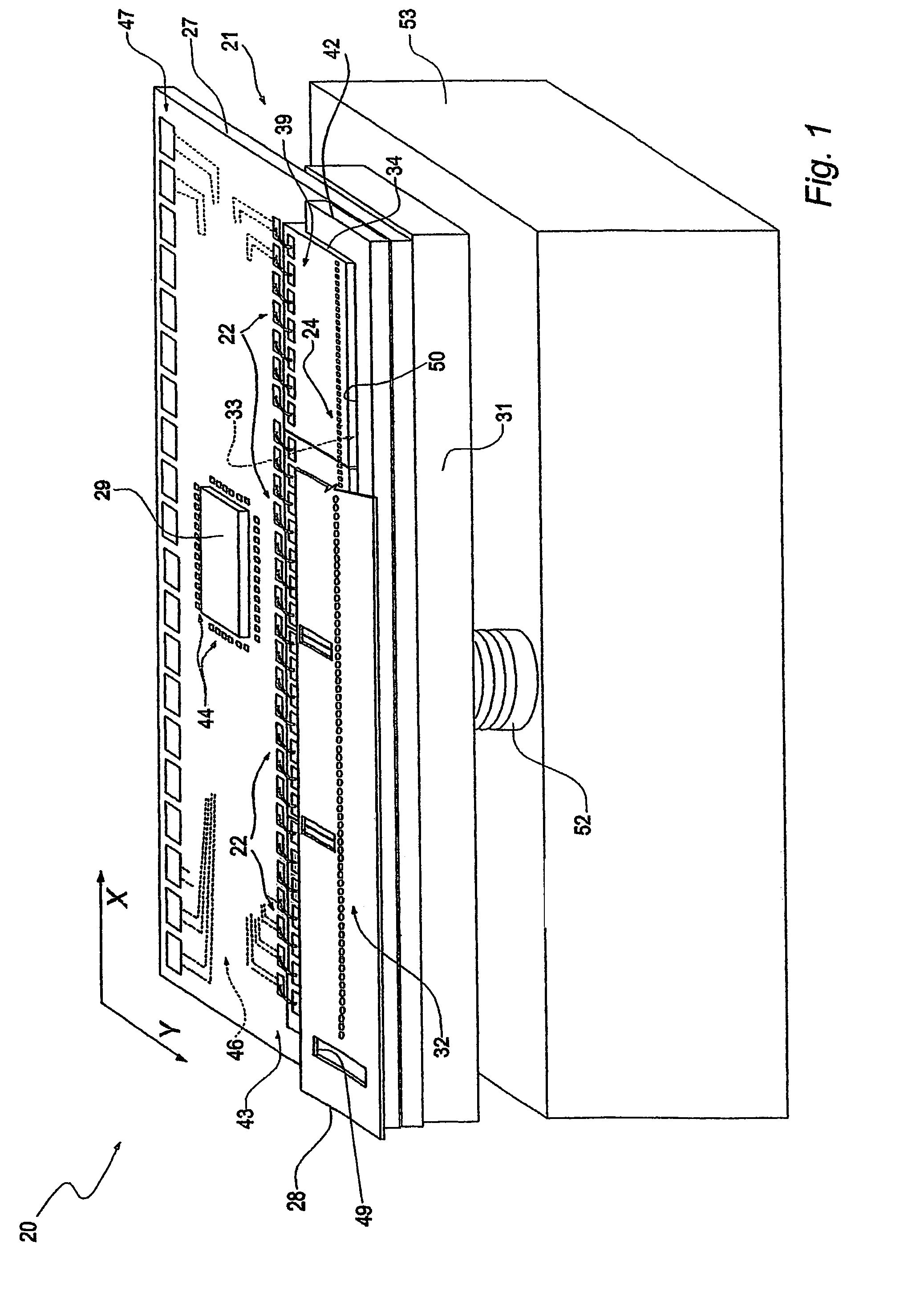
Depicted in FIG. 1, and designated with the numeral 20, in an upside-down position, is an ink jet printing device according to the invention for a printer not shown in any of the figures, with reference to an axis “X” parallel to the line of print and to an axis “Y” in the direction of feeding of the print medium.

The device 20 employs a head 21 of the serial-parallel type having a row of nozzles which extends in a main direction parallel to the line of printing of a page and in which the nozzles eject ...


PUM


Abstract

The printing device is ink jet, parallel or serial-parallel type and comprises a plurality of ejection modules each of which with ejection chambers suitable for containing ink and with associated relative heating elements for ink ejection control. The device includes a support and a nozzle plate common to the modules, and in which the support includes a base plate of rigid material that defines through its thickness a feeding duct for the ink which, in use, is substantially parallel to the line of printing (X axis) and the ejection modules are fixed side by side on the base plate and with the ejection chambers arranged in a line in the same direction (X axis), is a hydraulic, tight connection with the feeding duct. The nozzle plate is fixed on the ejection modules constituting an upper, hydraulically tight, closing surface, for the chambers and comprises a plurality of ejection nozzles in a line, in turn in hydraulic connection with corresponding cells of the modules.

Description

This application is a National Stage application of co-pending PCT application PCT / IT2003 / 000607 filed 8 Oct. 2003, which was published in the English language under PCT Article 21(2) on 22 Apr. 2004, and claims the benefit of Italian application number TO2002A00876 filed 10 Oct. 2002. The disclosures of each are expressly incorporated herein.TECHNICAL FIELDThis invention relates to parallel type, ink jet printing devices. More specifically, the invention relates to an ink jet printing device with a parallel type or serial-parallel type head comprising a plurality of ejection modules in accordance with the introductory part of claim 1.The invention has been developed with particular regard for application on a device in which heat energy is used to produce vapour bubbles in chambers filled with ink, resulting in the ejection of droplets of ink through relative nozzles.BACKGROUND ARTThermal type ink jet printing devices use heads having ejection modules which are usually made from wa...

Claims


Application Information

Patent Timeline
Patent Type & Authority Patents(United States)
IPC IPC(8): B41J2/175B41J2/17B41J2/14B41J2/145
CPCB41J2/14024B41J2/145B41J2202/20
Inventor CONTA, RENATOMANINI, ENRICO
Owner TELECOM ITALIA SPA
Why Eureka
Try Eureka