Transmission line with left-hand characteristics including a spiral inductive element

a technology of inductive element and transmission line, which is applied in the field of transmission lines, can solve the problems of increasing the overall size of the device, the inductance value cannot be changed according to a design condition, and the inductance value cannot be changed according to the design condition, so as to achieve the effect of improving the structure and increasing the inductance valu

Active Publication Date: 2012-07-31
KESPION CO LTD
View PDF31 Cites 7 Cited by
  • Summary
  • Abstract
  • Description
  • Claims
  • Application Information

AI Technical Summary

Benefits of technology

[0021]Accordingly, the present invention has been made in view of the above problems occurring in the prior art, and an object of the present invention is to provide a transmission line which can miniaturize a device and can increase an inductance value through improvement of a structure.
[0022]Another object of the present invention is to provide a transmission line whose shape can be designed freely in order to actively cope with required conditions.
[0027]The transmission line according to the present invention as constructed above has the following advantages.
[0028]First, the inductive elements are provided between both surfaces of the substrate. Accordingly, there is a benefit in that an inductance value can be changed in various ways. That is, a device can be miniaturized since a space utilization degree of the transmission line is increased. Further, an inductance value can be increased while minimizing the size of the transmission line.

Problems solved by technology

However, the above conventional transmission line has the following problems.
The value of the serial capacitor can vary by controlling an detailed shape of IDT, a distance between the elements and so on, but has many limitations in changing an inductance value in the inductor.
Accordingly, there was a problem in that the width of the substrate increases, resulting in an increase of the overall size of a device.
In this case, however, there was a problem in that the inductance value could not be changed according to a design condition since the width, material, etc. of the substrate are defined.

Method used


Image

  • Transmission line with left-hand characteristics including a spiral inductive element
  • Transmission line with left-hand characteristics including a spiral inductive element
  • Transmission line with left-hand characteristics including a spiral inductive element

Examples


first embodiment

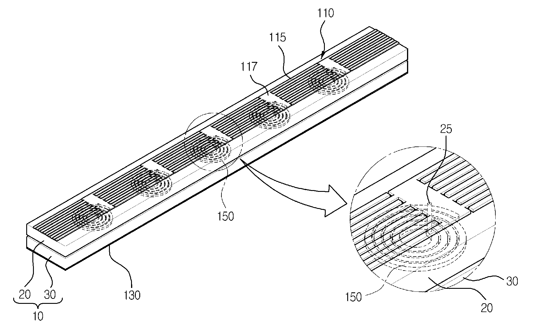
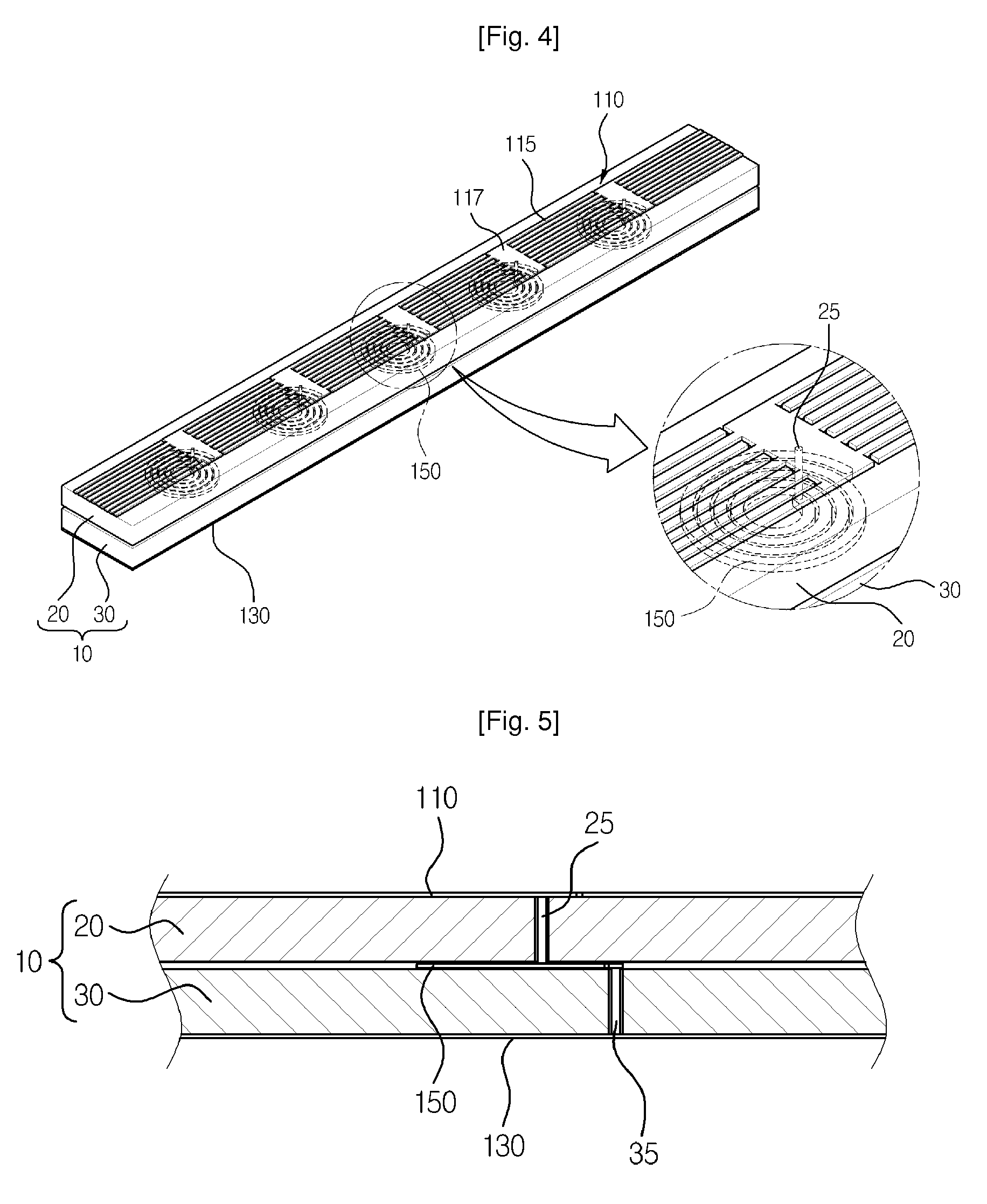
[0040]A construction of a transmission line according to the present invention will be described below with reference to FIGS. 4 to 6.

[0041]FIG. 4 is a perspective view schematically illustrating a transmission line according to a first embodiment of the present invention. FIG. 5 is a lateral view of FIG. 4. FIG. 6 is a perspective view illustrating an inductive element and a connection element of FIG. 4.

[0042]The transmission line in accordance with the present embodiment largely includes a transmission unit 110, a ground unit 130, and inductive elements 150, as shown in FIGS. 4 and 5.

[0043]As illustrated in FIGS. 4 and 5, the transmission unit 110 is provided on one surface of the substrate 10, and transmits an electrical signal. The substrate 10 can be preferably formed from a dielectric material having an insulating property. The transmission unit 110 can be formed from a thin metal element on the substrate 10 or can be formed by coating a conductive material on the substrate 10...

second embodiment

[0058]A construction of a transmission line according to the present invention will be described below with reference to FIGS. 7 and 8.

[0059]The present embodiment basically includes a transmission unit 210, a ground unit 230, and inductive elements 250 as in the first embodiment. The transmission unit 210 includes a capacitive element 215 and a stub 217, which are repeated, as shown in FIG. 8.

[0060]In contrast to the embodiment described with reference to FIGS. 4-6, in the embodiment illustrated in FIGS. 7 and 8, the inductive element 250 is formed to have a predetermined pattern within via holes 43 in the substrate 40.

[0061]In other words, as shown in FIG. 7, the top and bottom of the substrate 40 are both penetrated by the via holes 43, and the inductive elements 250 are formed in a predetermined pattern within the via holes 43.

[0062]The inductive element 250 is not limited to the above pattern shape. FIGS. 7 and 8 illustrate a shape in which the inductive element 250 has a helic...


PUM


Abstract

The present invention relates to a transmission line in which a physical value of an inductive element can be changed in various ways while minimizing a size. The transmission line of the present invention includes a transmission unit, a ground unit and inductive elements. The inductive element connects the transmission unit and the ground unit, and has a predetermined pattern. The inductive element is provided between two surfaces of a substrate. According to the present invention, a physical value of the inductive element, in particular, an inductance value can be changed in various ways while not increasing an overall size. Accordingly, a transmission line can be designed freely according to its application.

Description

CROSS REFERENCE TO RELATED APPLICATIONS[0001]This patent application is a U.S. National Phase application under 35 U.S.C. §371 of International Application No. PCT / KR2007 / 004015, filed on Aug. 22, 2007, entitled TRANSMISSION LINE, which claims priority to Korean patent application number 10-2006-0079326, filed Aug. 22, 2006.FIELD[0002]The present invention relates to a transmission line, and more particularly, to a transmission line which enables various modifications of physical values of inductive elements and miniaturization of a device through the improvement of a structure.BACKGROUND[0003]In general, a transmission line refers to a conductor system consisting of several conductors, and employing a propagation operation of a wave by electrical parameters, which are distributed between conductors, for example, such as resistance, inductance, conductance, and capacitance per unit length.[0004]Recently, active research has been conducted on methods of implementing a Left-Handed (LH...

Claims


Application Information

Patent Timeline
Patent Type & Authority Patents(United States)
IPC IPC(8): H01P3/08
CPCH01P3/081H01P3/00
Inventor RYOU, BYUNG HOONSUNG, WON MOYANG, MYO GUENKIM, JEONG PYO
Owner KESPION CO LTD
Why Eureka
Try Eureka