Muzzle loading rifle with removable breech plug

a breech plug and muzzle technology, applied in the field of muzzle-loading firearms, can solve the problems of clogging the threads, requiring significant time and effort to remove and replace the plug, and requiring a large number of turns, and achieve the effect of convenient removal for cleaning

Active Publication Date: 2012-09-11
SMITH & WESSON
View PDF42 Cites 8 Cited by
  • Summary
  • Abstract
  • Description
  • Claims
  • Application Information

AI Technical Summary

Benefits of technology

[0003]Muzzle loading rifles have an essentially closed breech at the rear of the barrel, so that powder and bullets must be loaded at the muzzle or forward end of the barrel. A typical muzzle loading rifle has a barrel with a breech plug attached to occupy an enlarged rear bore portion of the barrel at the breech end. In some rifles, the breech plug is permanently attached. In others, the breech plug is removable to facilitate pass-through cleaning of the bore.
[0005]A safer existing removable breech plug employs a finely threaded body that screws into the rear of the barrel, with 10-15 turns to secure it in place. This provides safety against hang fires and facilitates removal for cleaning. However, the number of turns requires significant undesirable time and effort to remove and replace the plug. Moreover, the fouling associated with muzzle loading rifles can clog the threads, requiring undesirably great torque to remove the plug, through the many rotations required.

Problems solved by technology

However, the number of turns requires significant undesirable time and effort to remove and replace the plug.
Moreover, the fouling associated with muzzle loading rifles can clog the threads, requiring undesirably great torque to remove the plug, through the many rotations required.
In addition, existing muzzle loading rifle breech plugs that use shotgun style primers do not fully support the primer used for firing.
This portion is unsupported, and presents a risk of rupture when firing, allowing unwanted fouling to occur.
Because unloading a muzzle loading rifle via the muzzle is difficult or time consuming without discharging the rifle, and requires special tools, some shooters may be tempted to leave a loaded rifle in an unsafe charged condition.
Conventional removable breach plugs may be used to unload via the breech, however these have the speed and convenience disadvantages noted above.

Method used


Image

  • Muzzle loading rifle with removable breech plug
  • Muzzle loading rifle with removable breech plug
  • Muzzle loading rifle with removable breech plug

Examples


Embodiment Construction

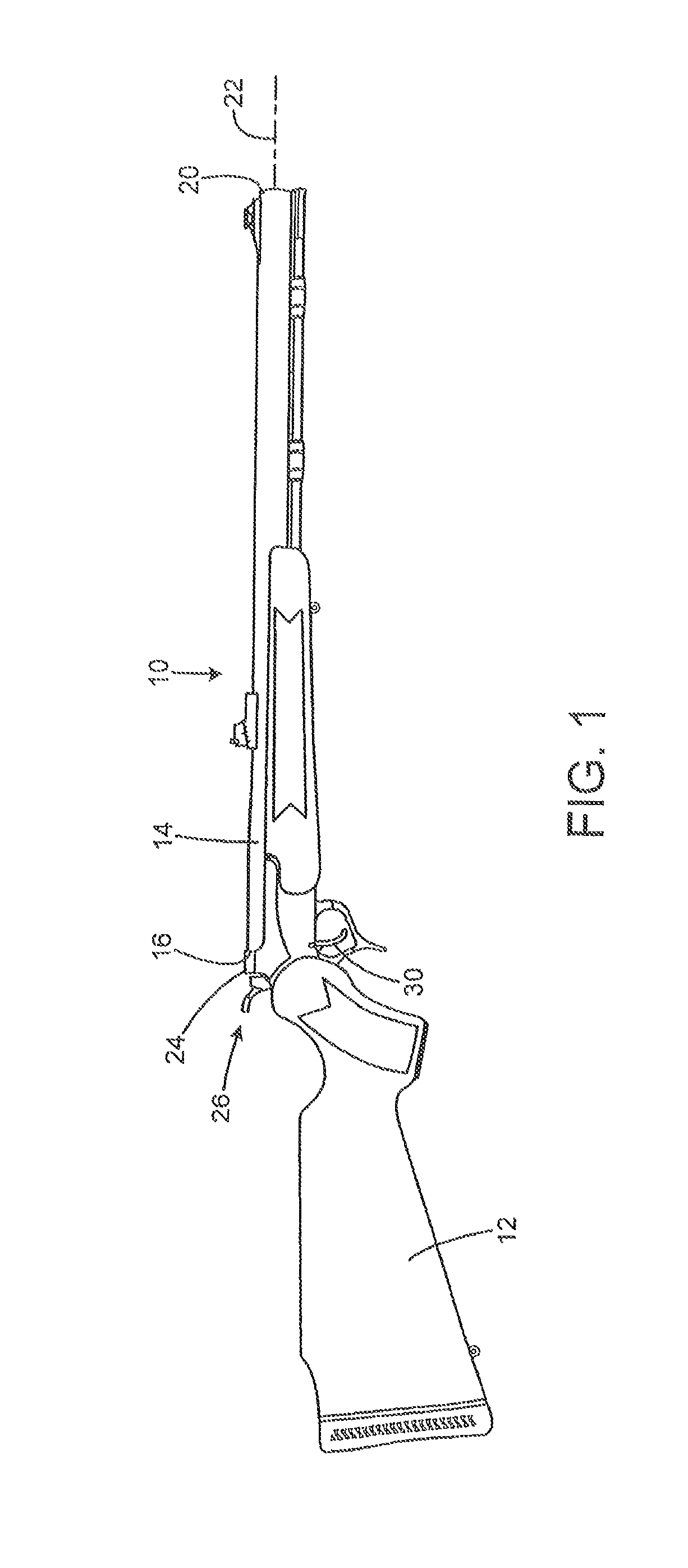
[0017]FIG. 1 shows a muzzle-loading firearm 10, with a stock 12 and a barrel 14 having a breech end 16 and a muzzle end 20, and having a bore defining a bore axis 22. A movable breech element 24 pivots between an open position and a closed (shown) position. A hammer 26 is pivotally connected adjacent the breech block to operate in response to operation of a trigger 30 as will be discussed below. A muzzle loading firearm having some similar features is disclosed in U.S. Pat. No. 6,604,311 to Laney et al., the disclosure of which is incorporated herein by reference.

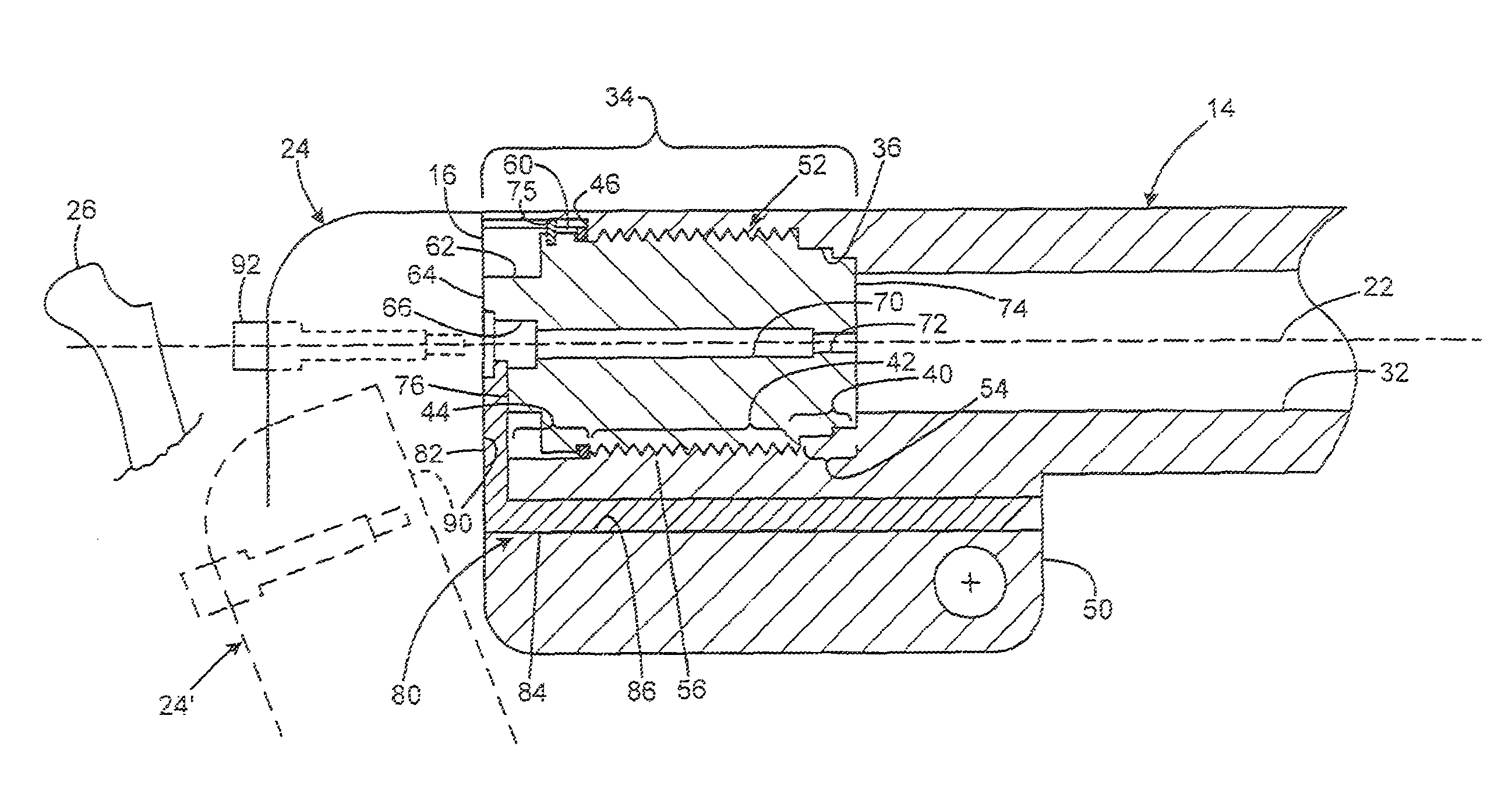
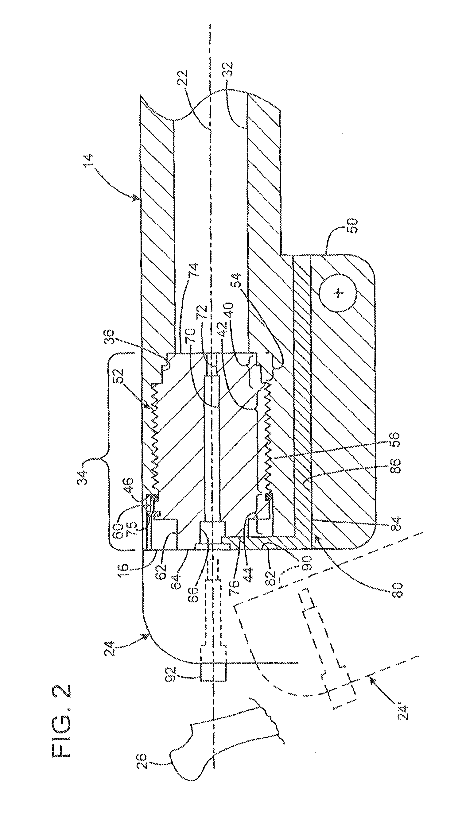
[0018]FIG. 2 shows the breech end 16 of the barrel 14. The barrel defines a rifled bore 32 (rifling not shown) that extends from the muzzle nearly the length of the barrel, except for a rear portion 34. The rear portion of the barrel defines an enlarged breech plug chamber 36 having a stepped initial portion 40, an internally threaded intermediate portion 42, and an enlarged clearance portion 44. A shoulder 46 is formed at ...


PUM


Abstract

A muzzle loading firearm has a barrel with a bore on a bore axis, and has a muzzle end and a breech end. A frame is connected to the barrel, and has a breech face. The frame moves between an open position in which the breech face is away from the breech end of the barrel, and a closed position in which the breech face abuts the breech end of the barrel. A breech plug is removably attached to the barrel, and is connected to the barrel by way of interrupted, or multistart threads, or locking lugs. The breech plug may have a rear face that abuts the breech face when the frame is closed, so that a primer contained in a primer pocket in the rear of the breech plug is fully supported on all sides.

Description

CROSS-REFERENCE TO RELATED APPLICATIONS[0001]This application is a Continuation-in-Part of, and claims priority to, U.S. patent application Ser. No. 11 / 316,116 entitled “MUZZLE LOADING RIFLE WITH REMOVABLE BREECH PLUG,” filed on Dec. 21, 2005, now U.S. Pat. 7,621,064, which is hereby incorporated by reference in its entirety.FIELD OF THE INVENTION[0002]This invention relates to firearms, and more particularly to muzzle loading firearms.BACKGROUND AND SUMMARY OF THE INVENTION[0003]Muzzle loading rifles have an essentially closed breech at the rear of the barrel, so that powder and bullets must be loaded at the muzzle or forward end of the barrel. A typical muzzle loading rifle has a barrel with a breech plug attached to occupy an enlarged rear bore portion of the barrel at the breech end. In some rifles, the breech plug is permanently attached. In others, the breech plug is removable to facilitate pass-through cleaning of the bore.[0004]One type of removable breech plug plus is one t...

Claims


Application Information

Patent Timeline
Patent Type & Authority Patents(United States)
IPC IPC(8): F41C9/08
CPCF41A3/18F41A3/30F41C9/08
Inventor LANEY, MARK C.GARLAND, GENE L.
Owner SMITH & WESSON
Why Eureka
Try Eureka