Muzzle loading firearm with removable breech cap

a breech cap and firearm technology, applied in the field of muzzle-loading firearms, can solve the problems of difficult reinstallation or removal of the plug after reinstallation, increased manufacturing cost and/or weight, and threads to become fouled, etc., to facilitate the cleaning of the bore through

Inactive Publication Date: 2010-08-17
SMITH & WESSON
View PDF24 Cites 2 Cited by
  • Summary
  • Abstract
  • Description
  • Claims
  • Application Information

AI Technical Summary

Benefits of technology

[0002]Muzzle loading rifles have an essentially closed breech at the rear of the barrel, so that powder and bullets must be loaded at the muzzle or forward end of the barrel. A typical muzzle loading rifle has a barrel with a breech plug attached to occupy an enlarged internally threaded rear bore portion of the barrel at the breech end. In some rifles, the breech plug is permanently attached. In others, the breech plug is removable to facilitate pass-through cleaning of the bore.
[0004]In addition, breech plugs are generally larger in diameter than the bore of the barrel. This means that the wall thickness surrounding the plug is thinner than it is just forward of the plug in the chamber. In at least some instances, this wall diameter at the plug may be a strength limitation, requiring a larger barrel diameter than otherwise would be required, increasing manufacturing cost and / or weight.
[0006]Further, the length of a breech plug must be greater than an adequate threshold to provide strength to retain the pressure in the chamber. This length extends the length of the barrel without extending the length from the breech face to the muzzle. The added barrel length increases the weight and cost without the performance advantages of a lengthened barrel.

Problems solved by technology

The fouled brush may pass over the internal threads at the breech, allowing the threads to become fouled.
This is a concern because the barrel threads are cut to a tight tolerance for a close fit with the plug threads, and minor fouling can make the plug difficult to reinstall or remove after reinstallation.
In at least some instances, this wall diameter at the plug may be a strength limitation, requiring a larger barrel diameter than otherwise would be required, increasing manufacturing cost and / or weight.
The added barrel length increases the weight and cost without the performance advantages of a lengthened barrel.
The plug itself has appreciable mass to fill the required length and diameter, with weight reducing measures being generally impractical, even though lightness is generally desired in many rifles.

Method used


Image

  • Muzzle loading firearm with removable breech cap
  • Muzzle loading firearm with removable breech cap
  • Muzzle loading firearm with removable breech cap

Examples


Embodiment Construction

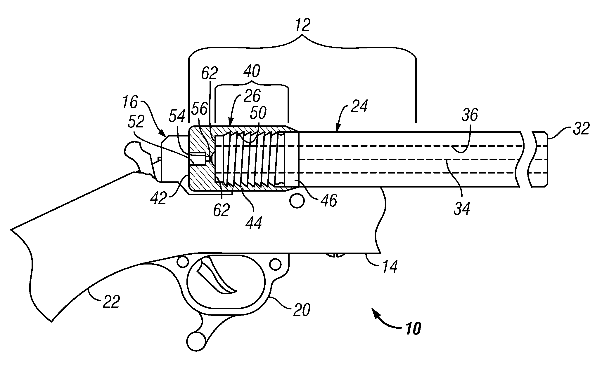
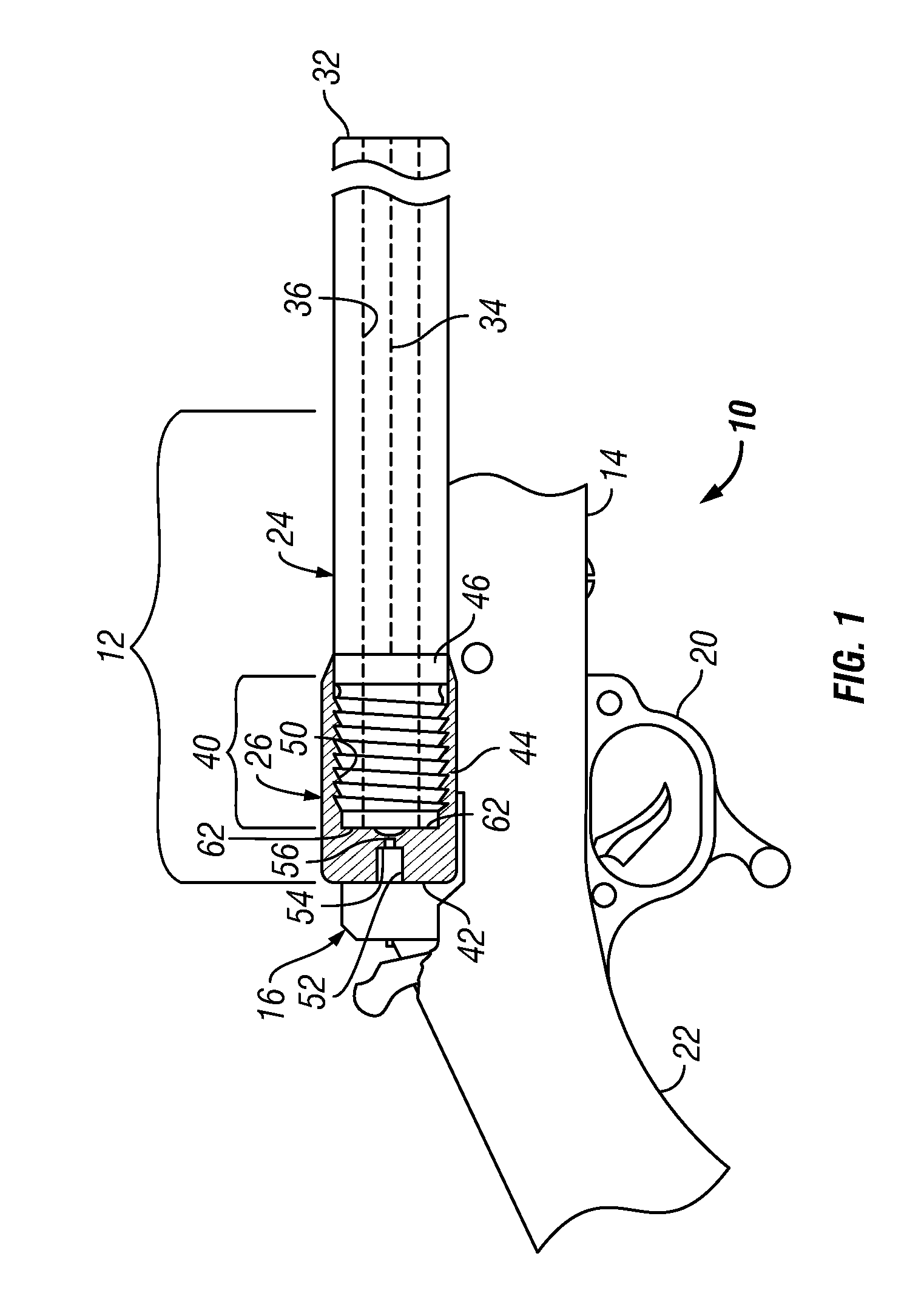
[0013]FIG. 1 shows a muzzleloading firearm 10 having a barrel assembly 12 with a connected forestock 14. A breech block 16, trigger assembly 20, and rear stock 22 are pivotally linked to the barrel.

[0014]The barrel assembly 12 includes a barrel 24 and a breech cap 26. The barrel has a muzzle end face 30 and a breach end face 32, each perpendicular to an axis 34 defined by the conventionally rifled bore 36. The bore extends for the entire length of the barrel, having a consistent profile from end to end. That is, it has a consistent diameter throughout the entire length defining a continuous cylinder, except for the variations inherent in conventional helical rifling. The grooves and lands of the rifling extend from end to end in the barrel, and each of the groove diameter and the land diameter remain constant throughout the length of the barrel.

[0015]A rear portion 40 of the length of the barrel nearest the breach end 32 is externally threaded to accommodate the removable breach 26....


PUM


Abstract

A muzzle loading firearm has an elongated barrel defining an elongated bore, with a muzzle end and a breech end. A breech cap is removably connected the breech end of the barrel to enclose a chamber at the rear of the bore. A portion of the breech cap may be external to the barrel, which may be externally threaded. The breech cap may be entirely clear of the breech bore, and the bore may have a consistent profile from end to end. The barrel threads may be standard, multistart or interrupted. The breech cap may overlay the face of the rear end of the barrel.

Description

FIELD OF THE INVENTION[0001]This invention relates to muzzle loading firearms, and more particularly to removable breech closures.BACKGROUND AND SUMMARY OF THE INVENTION[0002]Muzzle loading rifles have an essentially closed breech at the rear of the barrel, so that powder and bullets must be loaded at the muzzle or forward end of the barrel. A typical muzzle loading rifle has a barrel with a breech plug attached to occupy an enlarged internally threaded rear bore portion of the barrel at the breech end. In some rifles, the breech plug is permanently attached. In others, the breech plug is removable to facilitate pass-through cleaning of the bore.[0003]A typical removable breech plug employs a finely threaded elongated body that screws into the rear of the barrel, with 10-15 turns to secure it in place. The barrel's rear end is internally threaded to receive the plug, which removes for cleaning (not for normal loading operations.) The cleaning process involves the passing of a rod wi...

Claims


Application Information

Patent Timeline
Patent Type & Authority Patents(United States)
IPC IPC(8): F41C7/00
CPCF41A3/64F41C9/08
Inventor LANEY, MARK C.RITZ, GREGORY JAMES
Owner SMITH & WESSON
Why Eureka
Try Eureka