Magnetic head for perpendicular magnetic recording having a main pole and a shield

a perpendicular magnetic and magnetic recording technology, applied in the field of magnetic recording head perpendicular magnetic recording, can solve the problems of reducing the volume of the write shield, affecting the recording quality, so as to prevent the skew-induced problems and improve the write characteristics

Active Publication Date: 2013-04-23
HEADWAY TECH INC +1
View PDF9 Cites 49 Cited by
  • Summary
  • Abstract
  • Description
  • Claims
  • Application Information

AI Technical Summary

Benefits of technology

[0018]It is an object of the present invention to provide a magnetic head for perpendicular magnetic recording that is capable of preventing the skew-induced problems and providing improved write characteristics without compromising the function of the write shield.
[0028]In the magnetic head for perpendicular magnetic recording of the present invention, the angle that the second inclined surface forms relative to the direction perpendicular to the medium facing surface is greater than the angle that the first inclined surface forms relative to the direction perpendicular to the medium facing surface. Further, the distance between the main pole and an arbitrary point on the second inclined surface increases with decreasing distance between the arbitrary point and the fourth end. These features make it possible to prevent magnetic flux leakage from the main pole to the write shield while preventing magnetic flux saturation in the write shield. Consequently, according to the present invention, it is possible to prevent the skew-induced problems and provide improved write characteristics without compromising the function of the write shield.

Problems solved by technology

This makes it difficult for the main pole to direct much magnetic flux to the medium facing surface, thus leading to degradation of overwrite property.
The above-described configuration, however, has a problem in that where the inclined portion of the main pole and the inclined surface of the write shield are opposed to each other over a large area with a small spacing therebetween, magnetic flux leakage from the main pole to the write shield increases to cause degradation of write characteristics such as the overwrite property.
This, however, would result in a reduction in volume of the write shield and thereby compromise the function of the write shield.
More specifically, a reduction in volume of the write shield is likely to cause magnetic flux saturation in the write shield.
This in turn causes magnetic flux leakage from the write shield toward the medium facing surface, and thus raises a problem that the magnetic flux leakage may result in accidental erasure of data stored on the recording medium.
It has thus been difficult for a conventional magnetic head including a write shield to prevent the skew-induced problems and provide improved write characteristics without compromising the function of the write shield.

Method used


Image

  • Magnetic head for perpendicular magnetic recording having a main pole and a shield
  • Magnetic head for perpendicular magnetic recording having a main pole and a shield
  • Magnetic head for perpendicular magnetic recording having a main pole and a shield

Examples


first embodiment

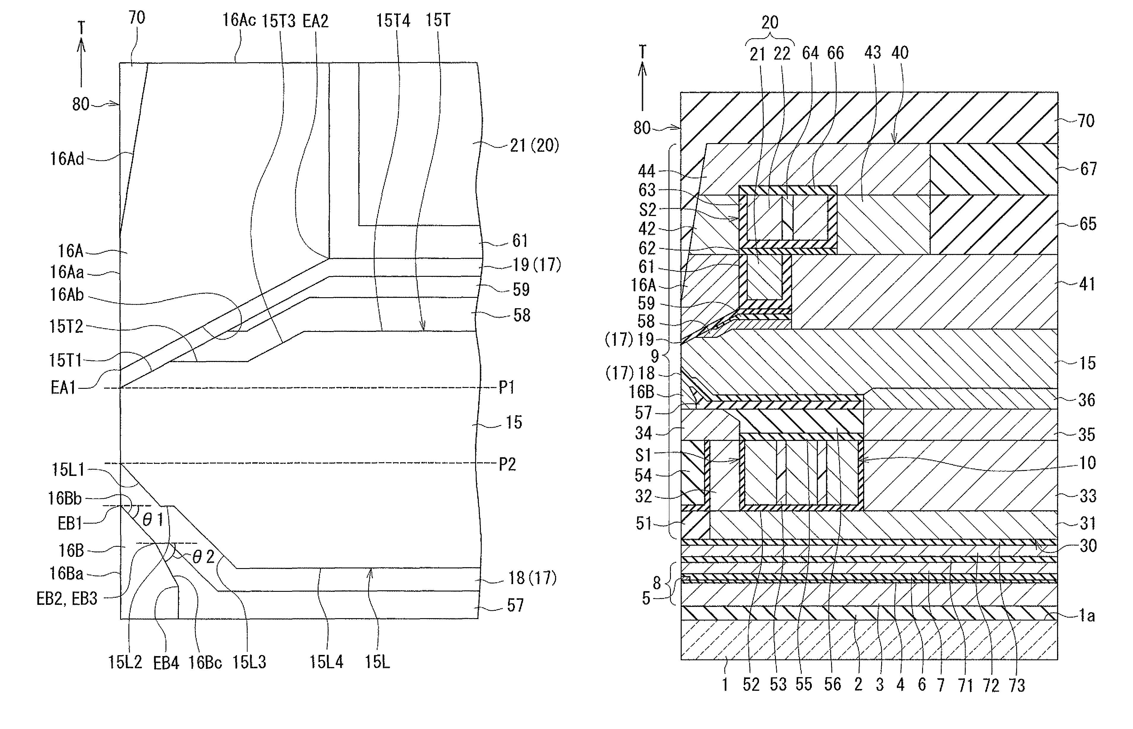
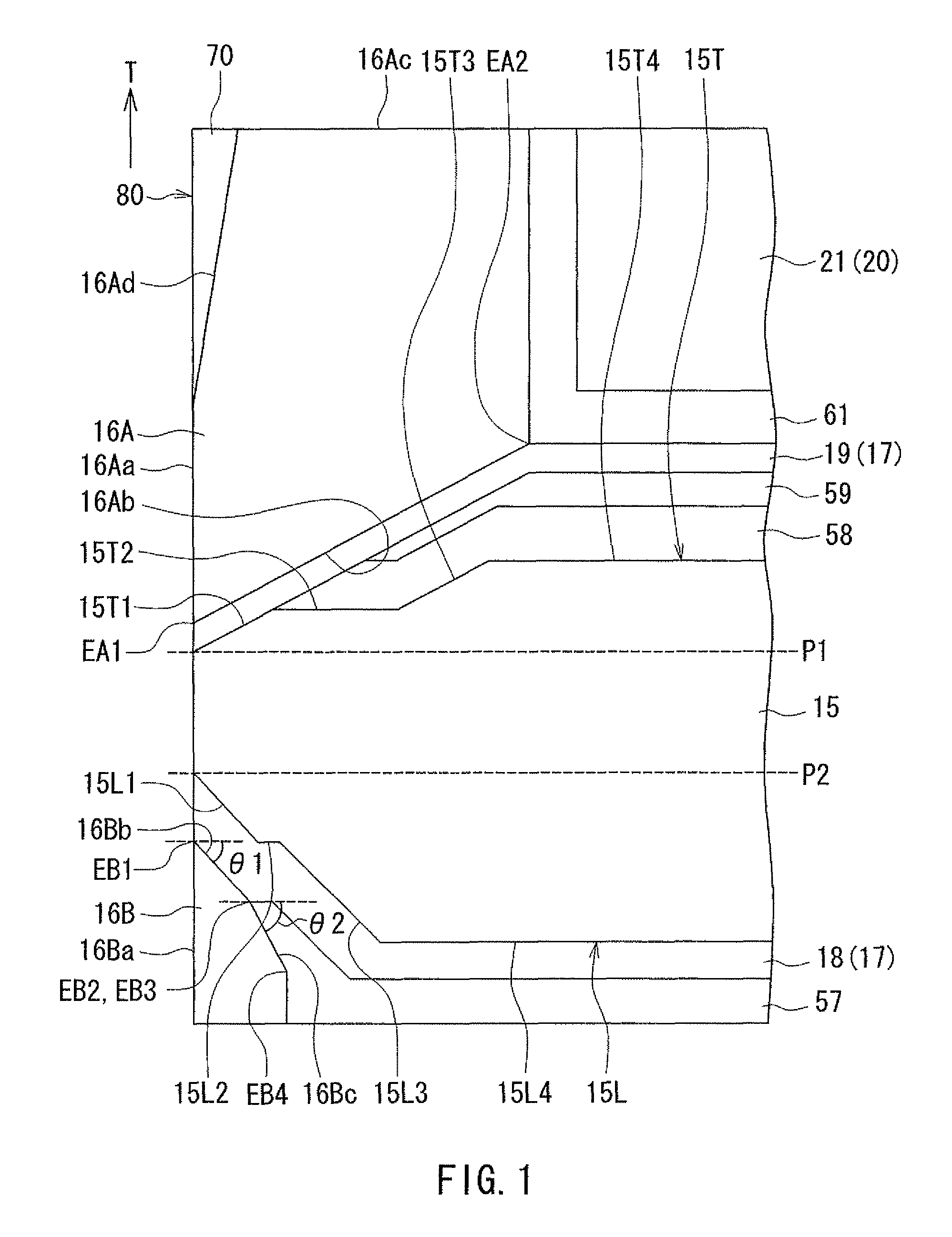
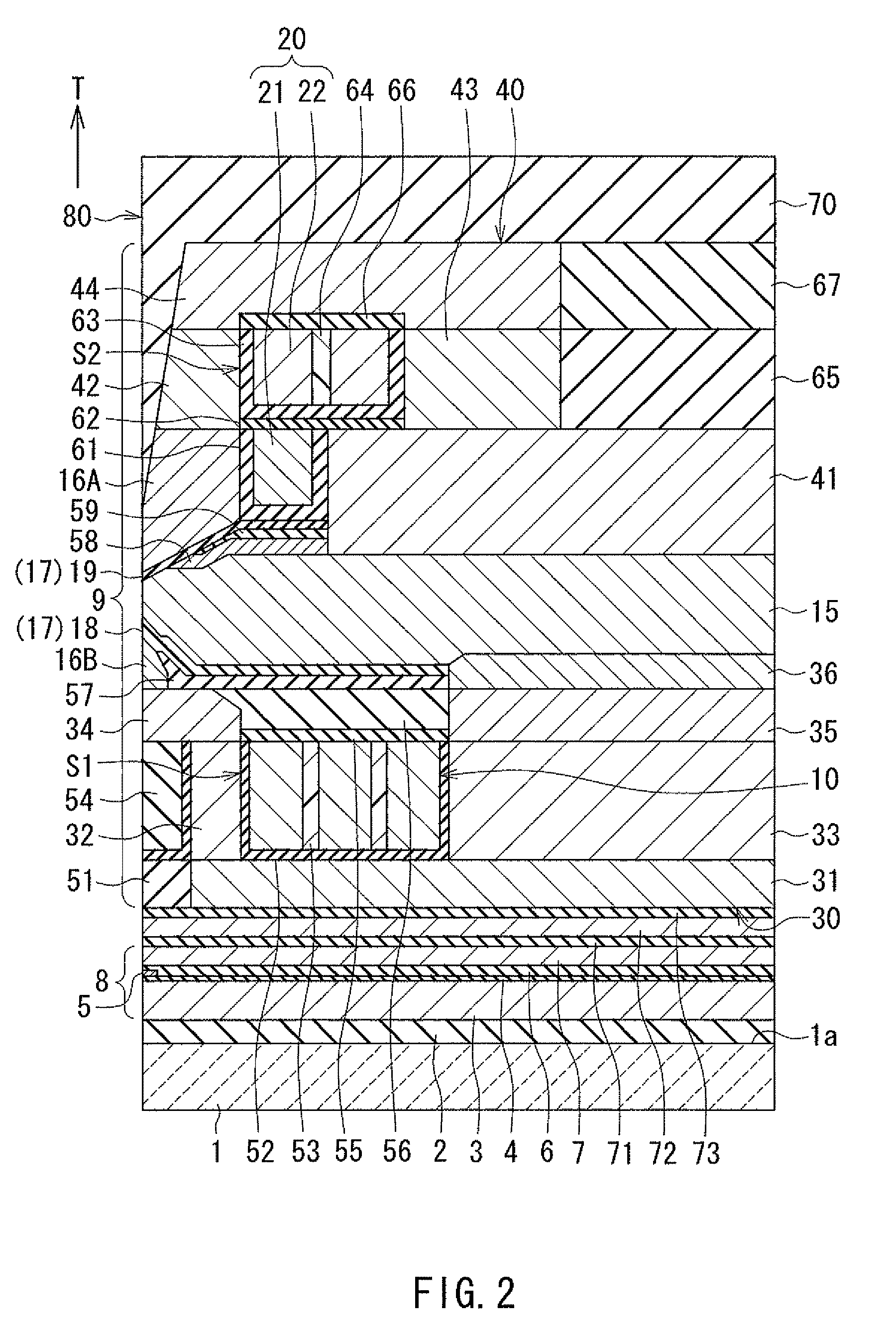
[0062]Embodiments of the present invention will now be described in detail with reference to the drawings. First, reference is made to FIG. 1 to FIG. 6 to describe the configuration of a magnetic head according to a first embodiment of the invention. FIG. 1 is a cross-sectional view showing a write shield and a portion of a main pole in the vicinity of the medium facing surface in the magnetic head according to the present embodiment. FIG. 2 is a cross-sectional view of the magnetic head according to the present embodiment. The arrows with the symbol T in FIG. 1 and FIG. 2 indicate the direction of travel of a recording medium. FIG. 3 is a front view showing the medium facing surface of the magnetic head according to the present embodiment. FIG. 4 is a plan view showing a first portion of a coil of the magnetic head according to the present embodiment. FIG. 5 is a plan view showing a first layer of a second portion of the coil of the magnetic head according to the present embodiment...

second embodiment

[0154]A magnetic head according to a second embodiment of the invention will now be described with reference to FIG. 23 to FIG. 25. FIG. 23 is a cross-sectional view showing the write shield and a portion of the main pole in the vicinity of the medium facing surface in the magnetic head according to the present embodiment. FIG. 24 is a cross-sectional view of the magnetic head according to the present embodiment. Note that FIG. 23 and FIG. 24 each show the main cross section. FIG. 25 is a front view showing the medium facing surface of the magnetic head according to the present embodiment.

[0155]The magnetic head according to the present embodiment is different from the magnetic head according to the first embodiment in the following respects. In the magnetic head according to the present embodiment, there are not provided the magnetic layers 34 and 35, the insulating layer 56, and the first connection layer. The second shield 16B is disposed over the magnetic layer 32 and the insula...

third embodiment

[0168]A magnetic head according to a third embodiment of the invention will now be described with reference to FIG. 31 and FIG. 32. FIG. 31 is a cross-sectional view showing the write shield and a portion of the main pole in the vicinity of the medium facing surface in the magnetic head according to the present embodiment. FIG. 32 is a cross-sectional view of the magnetic head according to the present embodiment. Note that FIG. 31 and FIG. 32 each show the main cross section.

[0169]The magnetic head according to the present embodiment is different from the magnetic head according to the second embodiment in the following respects. The magnetic head according to the present embodiment includes an insulating layer 60 made of an insulating material and disposed on the first gap layer 19 at a position away from the medium facing surface 80. The insulating layer 60 is interposed between the first gap layer 19 and each of the first shield 16A and the insulating film 61. The insulating laye...


PUM

PropertyMeasurementUnit
angleaaaaaaaaaa
angleaaaaaaaaaa
thicknessaaaaaaaaaa

Abstract

A magnetic head with a main pole is provided. The main pole has a bottom end including an inclined portion. A write shield has a first inclined surface opposed to the inclined portion and a second inclined surface that is located farther from a medium facing surface than is the first inclined surface. The first inclined surface has a first end located in the medium facing surface and a second end opposite thereto. The second inclined surface has a third end connected to the second end and a fourth end opposite thereto. The second inclined surface forms a greater angle than does the first inclined surface relative to a direction perpendicular to the medium facing surface. The distance between the main pole and an arbitrary point on the second inclined surface increases with decreasing distance between the arbitrary point and the fourth end.

Description

BACKGROUND OF THE INVENTION[0001]1. Field of the Invention[0002]The present invention relates to a magnetic head for perpendicular magnetic recording that is used for writing data on a recording medium by means of a perpendicular magnetic recording system, and more specifically, to a magnetic head for perpendicular magnetic recording that has a main pole and a shield.[0003]2. Description of Related Art[0004]The recording systems of magnetic read / write apparatuses include a longitudinal magnetic recording system wherein signals are magnetized in a direction along the plane of a recording medium (the longitudinal direction) and a perpendicular magnetic recording system wherein signals are magnetized in a direction perpendicular to the plane of a recording medium. It is known that the perpendicular magnetic recording system is harder to be affected by thermal fluctuation of the recording medium and capable of providing higher linear recording density, compared with the longitudinal mag...

Claims


Application Information

Patent Timeline
Patent Type & Authority Patents(United States)
IPC IPC(8): G11B5/147
CPCG11B5/1278G11B5/3116G11B5/3146G11B5/315
Inventor SASAKI, YOSHITAKAITO, HIROYUKISATO, KAZUKIARAKI, HIRONORITANEMURA, SHIGEKISHIMIZU, TATSUYA
Owner HEADWAY TECH INC
Why Eureka
Try Eureka