Light guide plate, surface light source device and transmissive display apparatus

a technology of light guide plate and surface light source device, which is applied in the direction of mechanical devices, lighting and heating apparatus, instruments, etc., can solve the problems of reducing the brightness of the front surface, deteriorating the image, and reducing the convergence of light, so as to increase the brightness, increase the brightness, and increase the brightness

Active Publication Date: 2013-10-08
DAI NIPPON PRINTING CO LTD
View PDF8 Cites 7 Cited by
  • Summary
  • Abstract
  • Description
  • Claims
  • Application Information

AI Technical Summary

Benefits of technology

[0011]A problem to be solved by the present invention is to provide a light guide plate with high in-plane uniformity of brightness and high light convergence that facilitates a further reduction in thickness, and a surface light source device and a transmissive display apparatus provided with this light guide plate.
[0030](8) Since the transmissive display apparatus includes the surface light source device according to the present invention and the transmissive display unit that is illuminated by the surface light source device from the backside, it is possible to provide a display of a superior image in which the front surface brightness is high, the in-plane uniformity of brightness is high, and the Moire phenomenon is reduced as much as possible. In addition, the transmissive display apparatus can be reduced in thickness.

Problems solved by technology

However, the conventional surface light source device of the edge lighting type tends to be brighter on the light source side and darker as being away from the light source in the light guiding direction, since an amount of light emitted in the light guiding direction is not sufficiently uniform.
Such unevenness of light intensity leads to unevenness of brightness of an image displayed on the transmissive display apparatus, causing a deterioration of the image.
However, in such a light guide plate with the diffusion patterns, light exits after being diffusely reflected on the reflective surface, leading to problems of reduced convergence of the light and reduced front surface brightness.

Method used


Image

  • Light guide plate, surface light source device and transmissive display apparatus
  • Light guide plate, surface light source device and transmissive display apparatus
  • Light guide plate, surface light source device and transmissive display apparatus

Examples


first embodiment

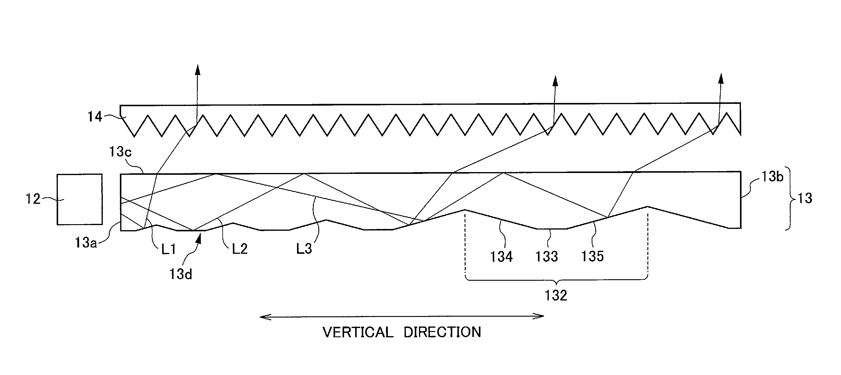
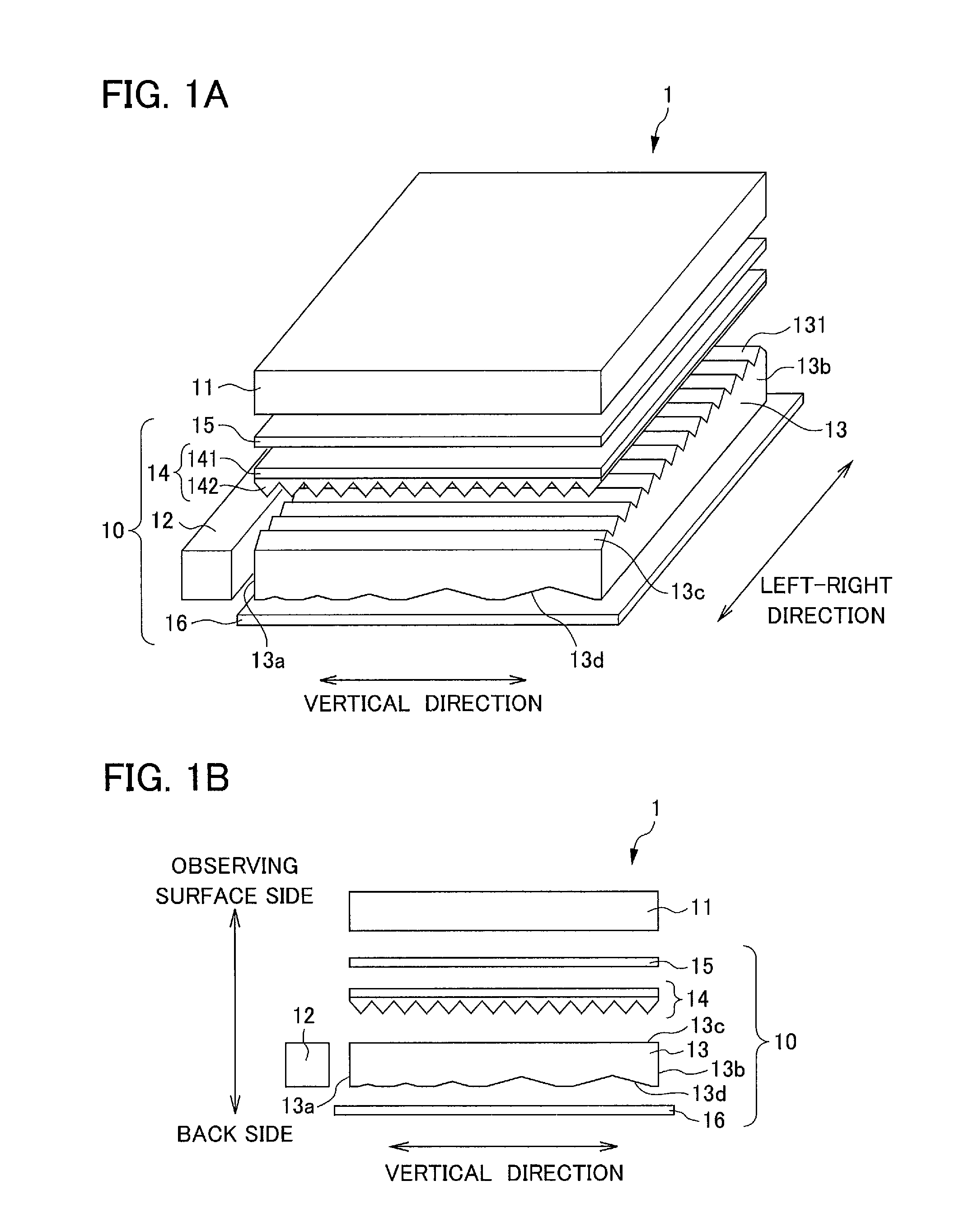
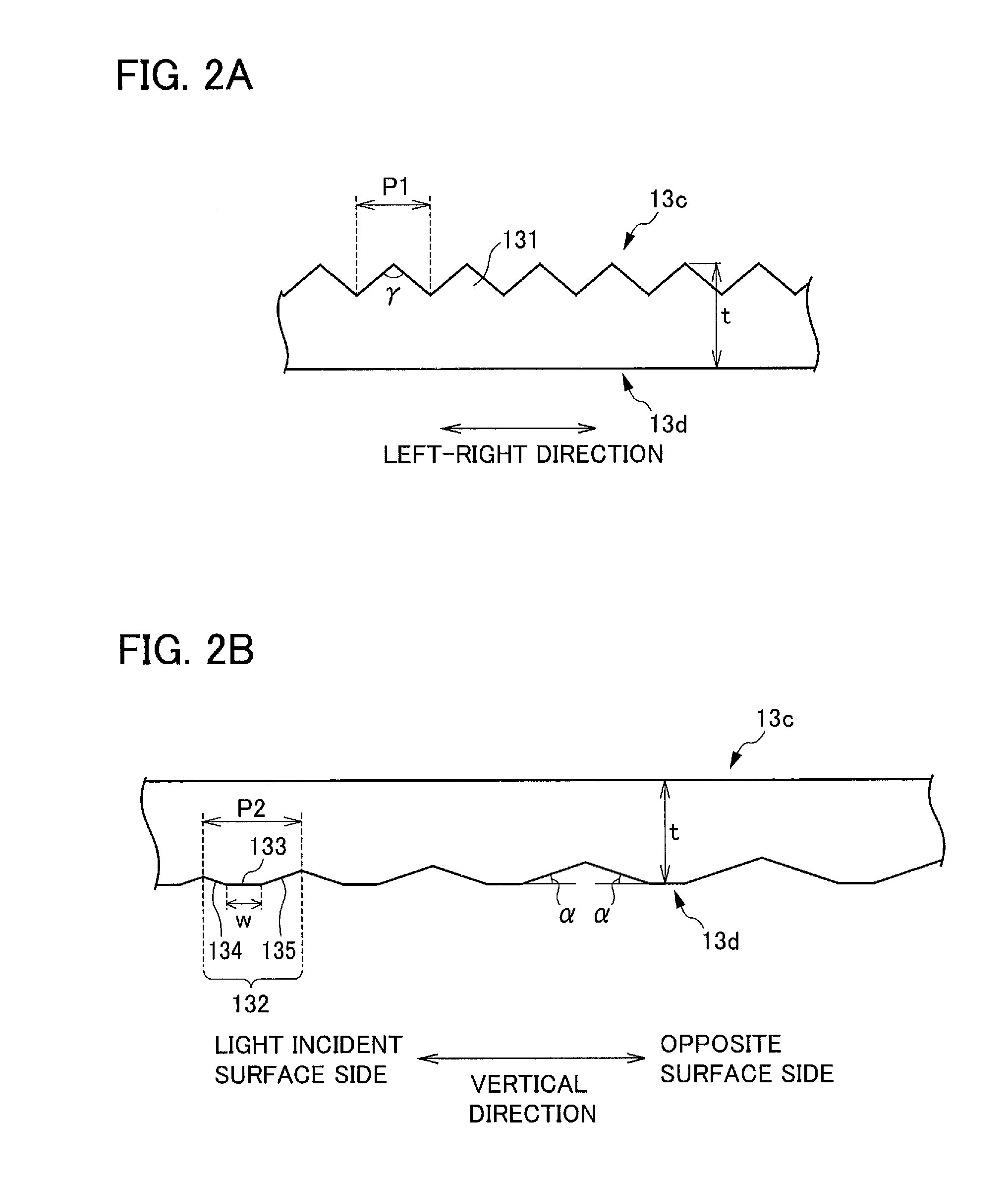
[0044]FIG. 1 is a diagram illustrating a configuration of a display apparatus 1 and a surface light source device 100 according to a first embodiment. FIG. 1A is a perspective view of the display apparatus 1 and the surface light source device 10 according to the first embodiment; and FIG. 1B is a cross-sectional view of the display apparatus 1 and the surface light source device 10 according to the first embodiment.

[0045]The display apparatus 1 is a liquid crystal transmissive display apparatus including a Liquid Crystal Display (LCD) panel 11, a light source unit 12, a light guide plate 13, a prism sheet 14, a light diffusive sheet 15, a reflector 16 and the like. In the display apparatus 1, image information formed on the LCD panel 11 is displayed by illuminating the LCD panel 11 from behind. In the display apparatus 1, the light source unit 12, the light guide plate 13, the prism sheet 14, the light diffusive sheet 15 and the reflector 16 together correspond to the surface light...

second embodiment

[0105]FIG. 4 is a diagram illustrating a shape of a light guide plate 23 according to a second embodiment. FIG. 4A is a diagram illustrating a cross-section that is orthogonal to a sheet surface of the light guide plate 23 and parallel to a direction of arrangement of optical units 232 (vertical direction); and FIG. 4B is an enlarged view of a part of the cross-section illustrated in FIG. 4A.

[0106]The light guide plate 23 of the second embodiment is configured substantially similar to the light guide plate 13 of the first embodiment, except that a shape of optical units 232 formed on a reflective surface 23d is different from that of the first embodiment. Therefore, portions having functions similar to the light guide plate 13 of the first embodiment are referred to by the same symbols or symbols bearing the same symbols in last part, and specific descriptions thereof are omitted accordingly.

[0107]In addition, the light guide plate 23 of the second embodiment is usable in the surfac...

third embodiment

[0122]FIGS. 6A and 6B are diagrams each illustrating a display apparatus 3 and a surface light source device 30 according to a third embodiment. FIG. 6A is a perspective view of the display apparatus 3 and the surface light source device 30 according to the third embodiment; and FIG. 6B is a cross-sectional view of the display apparatus 3 and the surface light source device 30 according to the third embodiment.

[0123]The display apparatus 3 and the surface light source device 30 are configured substantially similar to the display apparatus 1 and the surface light source device 10 of the first embodiment except for two light source units 32A, 32B and a light guide plate 33. Therefore, portions with similar functions to the first embodiment are referred to by the same symbols or symbols bearing the same symbols in last part, and specific descriptions thereof are omitted accordingly.

[0124]The display apparatus 3 is provided with an LCD panel 11 and the surface light source device 30.

[01...


PUM


Abstract

A light guide plate shaped substantially like a plate includes a light incident surface, a light exit surface and a reflective surface, which is opposite to the light exit surface, configured to reflect light toward the light exit surface. A plurality of optical units is arranged along the reflective surface in a direction orthogonal to the light incident surface. Each optical unit is shaped substantially like a quadratic prism that is convex toward the reflective surface and has a top surface and two slopes being formed opposite to each other with respect to the top surface. A dimension of the top surface is constant in a direction of arrangement of the optical units and an interval between adjacent optical units becomes greater as the adjacent optical units lie further away from the light incident surface in the direction of arrangement of the optical units.

Description

[0001]This application is based on and claims the benefit of priority from Japanese Patent Application No. 2011-025454, filed on 8 Feb. 2011, the content of which is incorporated herein by reference.BACKGROUND OF THE INVENTION[0002]1. Field of the Invention[0003]The present invention relates to a light guide plate, and a surface light source device and a transmissive display apparatus that are provided with the light guide plate.[0004]2. Related Art[0005]A transmissive display apparatus has been known that displays an image by illuminating a transmissive display unit such as a Liquid Crystal Display (LCD) panel from a backside thereof by a surface light source device (back light). Surface light source devices can be roughly classified into a direct lighting type in which a light source is disposed directly below an optical member and an edge lighting type in which a light source is disposed on a side of an optical member. A surface light source device of the edge lighting type has b...

Claims


Application Information

Patent Timeline
Patent Type & Authority Patents(United States)
IPC IPC(8): F21V8/00G02B6/42G02B6/00
CPCG02B6/0038G02B6/0061
Inventor GOTOU, MASAHIROSEKIGUCHI, HIROSHIYAMAMOTO, HIROSHI
Owner DAI NIPPON PRINTING CO LTD
Why Eureka
Try Eureka