Configuration for an image forming apparatus having an upright recording medium storage unit

a technology of image forming apparatus and recording medium, which is applied in the direction of electrographic process apparatus, typewriters, instruments, etc., can solve the problems of heat generation at the fixing device rising to the developer unit, disadvantageous heating of the developer unit, and so as to prevent heat deterioration of the developer, increase the operationality of the apparatus, and facilitate the loading of papers

Active Publication Date: 2013-12-03
BROTHER KOGYO KK
View PDF26 Cites 1 Cited by
  • Summary
  • Abstract
  • Description
  • Claims
  • Application Information

AI Technical Summary

Benefits of technology

[0009]With this configuration of the image forming apparatus, because the fixing device is arranged above the developer unit at least including the developer carrier, the developer unit is not heated by the heat generated and rising from the fixing device. This can prevent heat deterioration of the developer.
[0010]Further, because the paper conveyance passage extends upward from the lower portion of the recording sheet storage unit toward the recording sheet receiving unit, it is possible to restrict an increase in the vertical size of the image forming apparatus around the recording sheet storage unit when compared with the conventional apparatus in which the paper conveyance passage extends downward from the lower part of the recording sheet storage unit. This is advantageous because the user can easily load papers into the recording sheet storage unit and the operationality of the apparatus increases as a result.
[0011]According to the present invention, it is possible to prevent heat deterioration of the developer due to heat generated and rising from the fixing device. It is also possible to reduce the size of the whole apparatus in the vertical direction.

Problems solved by technology

However, in this image forming apparatus, because the fixing device is positioned below the developer unit, heat generated at the fixing device rises to the developer unit.
This may cause the developer unit to be heated disadvantageously, and as a result heat deterioration of the developer may occur.
Therefore, it becomes difficult to load papers into the paper feed tray, which leads to deteriorated operationality of the image forming apparatus.

Method used


Image

  • Configuration for an image forming apparatus having an upright recording medium storage unit
  • Configuration for an image forming apparatus having an upright recording medium storage unit
  • Configuration for an image forming apparatus having an upright recording medium storage unit

Examples


Embodiment Construction

[0021]With reference to the attached drawings, one preferred embodiment of an image forming apparatus according to the present invention will be described below.

Exterior of Printer

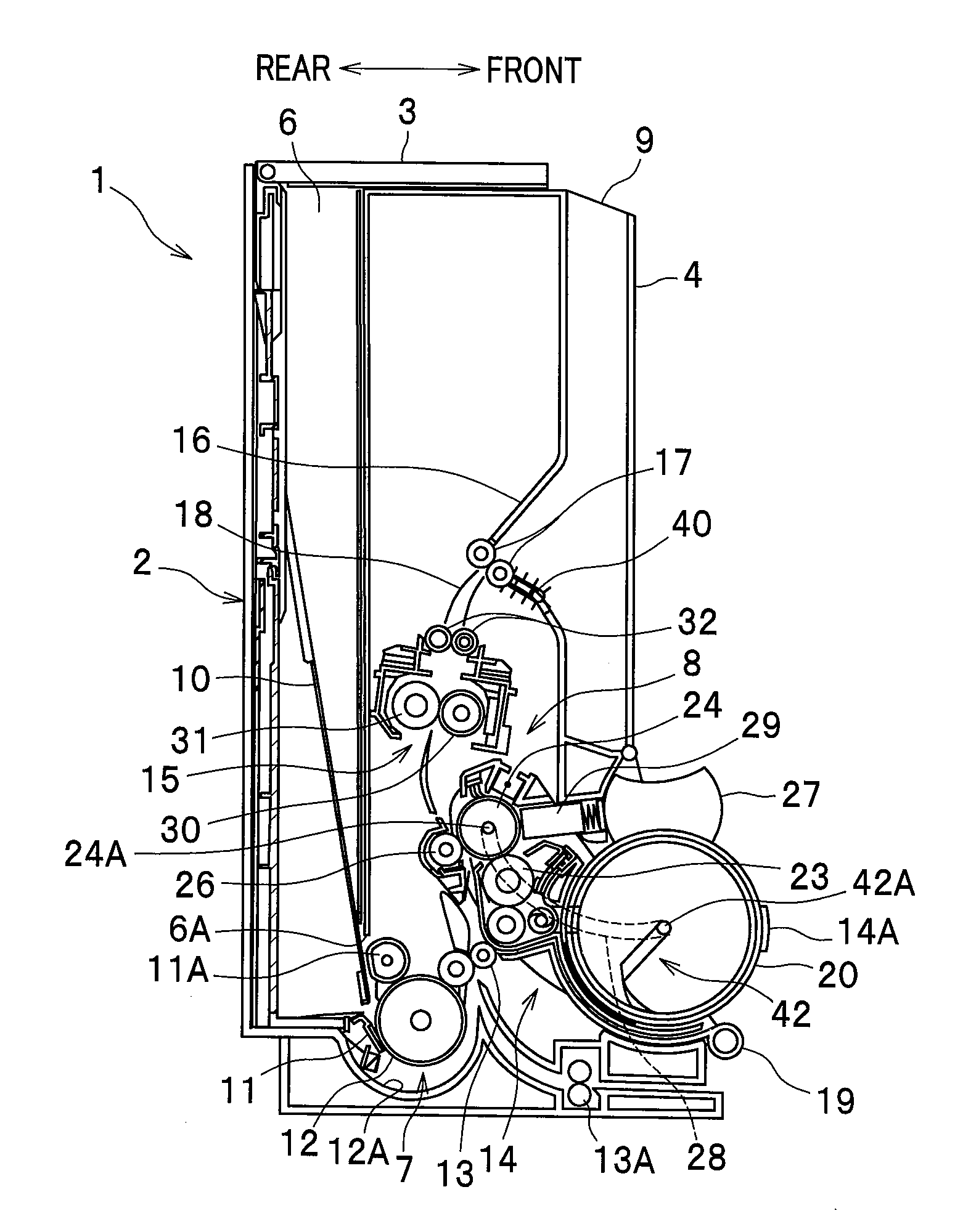
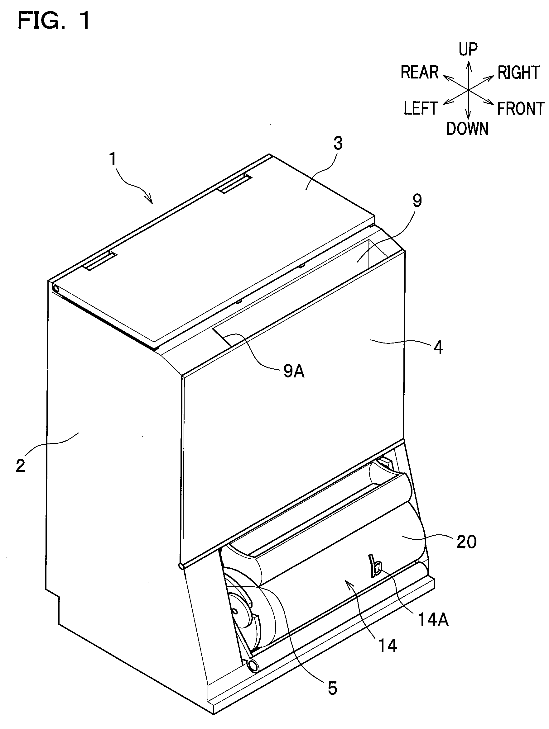
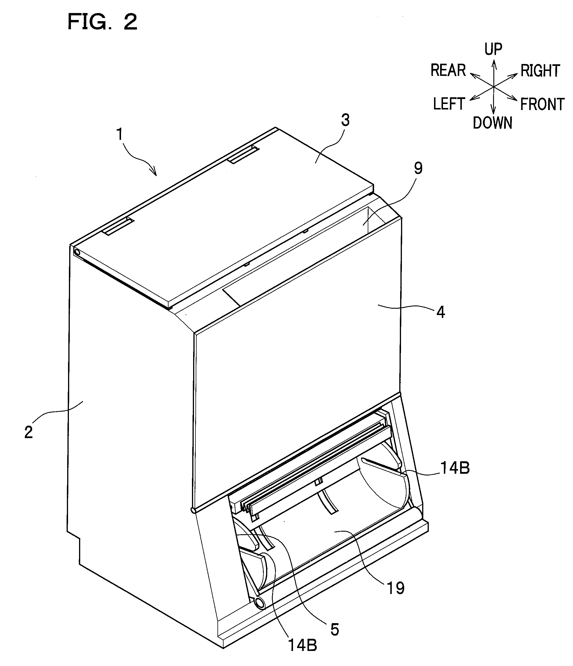
[0022]As seen in FIGS. 1 and 2, an image forming apparatus according to one embodiment of the present invention is provided as an upright-type printer 1, which has a relatively short length in the front-back direction compared to the right-and-left direction and the height of which is tall. The printer 1 has a main body casing 2. A top cover 3 is provided at an upper part of the main body casing 2, and a front cover 4 is provided at a front upper part of the main body casing 2. Provided at a front lower part of the main body casing 2 is a detachment opening 5 for attachment / detachment of a process cartridge 14 and a toner cartridge 20, which constitute an image forming unit 8 to be described later.

Internal Structure of Printer

[0023]As seen in FIG. 3A, the main body casing 2 includes therein a paper feed tr...


PUM


Abstract

An image forming apparatus includes a recording sheet storage unit for storing recording sheets substantially in an upright position, an image forming unit which forms an image on a recording sheet conveyed from the recording sheet storage unit, and a recording sheet receiving unit for storing the recording sheet conveyed from the image forming unit substantially in an upright position. In this image forming apparatus, a paper conveyance passage for conveying the recording sheet extends upward from a lower portion of the recording sheet storage unit toward the recording sheet receiving unit. The image forming unit positioned on the paper conveyance passage comprises a fixing device and a developer unit at least including a developer carrier, and the fixing device is arranged above the developer unit.

Description

CROSS REFERENCE TO RELATED APPLICATIONS[0001]This application claims the foreign priority benefit under Title 35, United States Code, §119(a)-(d) of Japanese Patent Application No. 2007-091876 filed on Mar. 30, 2007 in the Japan Patent Office, the disclosure of which is herein incorporated by reference in its entirety.BACKGROUND OF THE INVENTION[0002]The present invention relates to an image forming apparatus such as a printer.[0003]As an image forming apparatus such a printer, an upright-type image forming apparatus is generally known. For example, Japanese Laid-open Patent Application No. 2003-302889 discloses such an upright-type image forming apparatus, in which a paper feed tray (recording sheet storage unit) for storing papers as recording sheets and a paper output tray (recording sheet receiving unit) are arranged back and forth with these trays positioned upright.[0004]In this image forming apparatus, the paper feed tray is arranged higher than the paper output tray, so that...

Claims


Application Information

Patent Timeline
Patent Type & Authority Patents(United States)
IPC IPC(8): G03G15/00
CPCG03G21/20G03G21/1609G03G21/1685G03G15/6502G03G2221/1639G03G2221/1678
Inventor SATO, SHOUGOKATAYAMA, SHIGEHARUHANAI, MITSUKO
Owner BROTHER KOGYO KK
Why Eureka
Try Eureka