Drag-reducing device

a technology of drag reduction device and drag reduction, which is applied in the direction of vehicle body streamlining, monocoque construction, vehicle body structure, etc., can solve the problems of increasing the amount of fuel consumption required for transportation, direct increase in operating costs, and transport vehicles, such as trucks, are susceptible to aerodynamic drag, so as to reduce energy costs and reduce drag and turbulence.

Active Publication Date: 2013-12-17
VISENTIN FRANK
View PDF10 Cites 32 Cited by
  • Summary
  • Abstract
  • Description
  • Claims
  • Application Information

AI Technical Summary

Benefits of technology

[0010]In one aspect of the present invention, there is provided an apparatus for reducing drag on a transport vehicle, the apparatus comprising a plurality of aerodynamic panels deployed in a direction opposite of travel of the vehicle, wherein each of the panels retracting into housing located adjacent to planar surfaces of the vehicle, wherein the aerodynamic panels are deployed and retracted in a coordinated manner, and when deployed, the panels are in contact with each other to provide a continuous aerodynamic design.
[0020]The apparatus comprises retractable aerodynamic panels at the rear of the tractor cabin. When these panels are deployed, they provide an aerodynamic design in between the tractor cabin and front end of a trailer attached to the tractor, thereby reducing drag and turbulence as the vehicle travels, for example, down a highway, which in turn, reduces energy costs associated with transportation. When not in use and at low speed when the drag is minimal or negligible, the panels retract adjacent to the side and top of the vehicle. An automated system retracts the panels below a predetermined speed. The deployed flexible panels allow for turns at highway speed. The retracted panels are housed either on the outside surface of the vehicle; the inside surface of the vehicle, or within the walls of the vehicle.

Problems solved by technology

As a vehicle increases its speed, so too does the amount of aerodynamic drag, which in turn, increases the amount of fuel consumption required for transport.
This inefficiency leads to a direct increase in operating costs.
As a result, there have been many efforts to reduce aerodynamic drag, particularly on transport vehicles which are not sufficiently streamlined to minimize aerodynamic drag.
In particular, transport vehicles, such as trucks, are susceptible to aerodynamic drag, due to the shape of the cabin and / or trailer.
This apparatus requires a complex series of mechanical linkages.
Furthermore, these devices are not easily adapted for reducing the aerodynamic drag in the space between the rear of a cabin and the front surface of an attached trailer.
The apparatus is bulky when fully deployed, and is attached to the rear doors of the vehicle.
Such an apparatus cannot be easily adapted to providing drag reduction in the space between a cabin and an attached trailer.
In addition, the nesting elements require a large number of complex mechanical linkages for operation.

Method used


Image

  • Drag-reducing device
  • Drag-reducing device
  • Drag-reducing device

Examples


Embodiment Construction

[0040]The following is given by way of illustration only and is not to be considered limitative of this invention. Many apparent variations are possible without departing from the spirit and scope thereof.

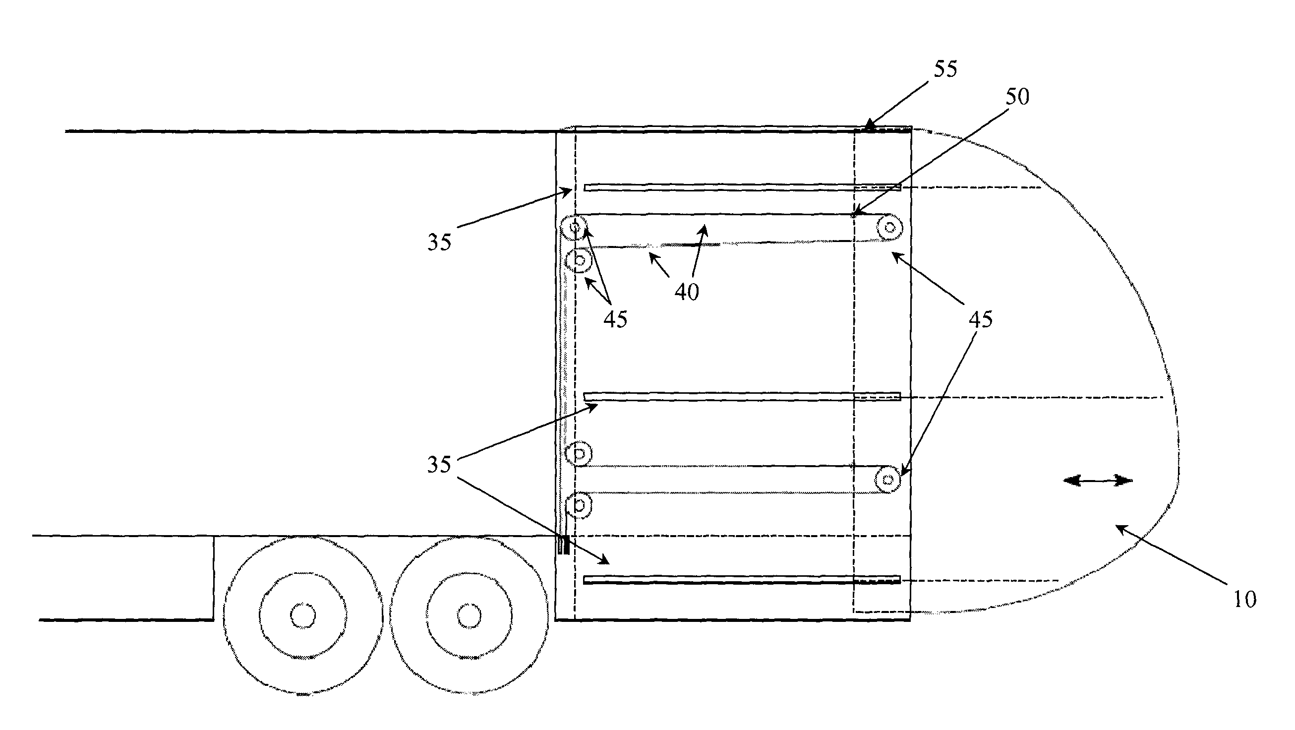
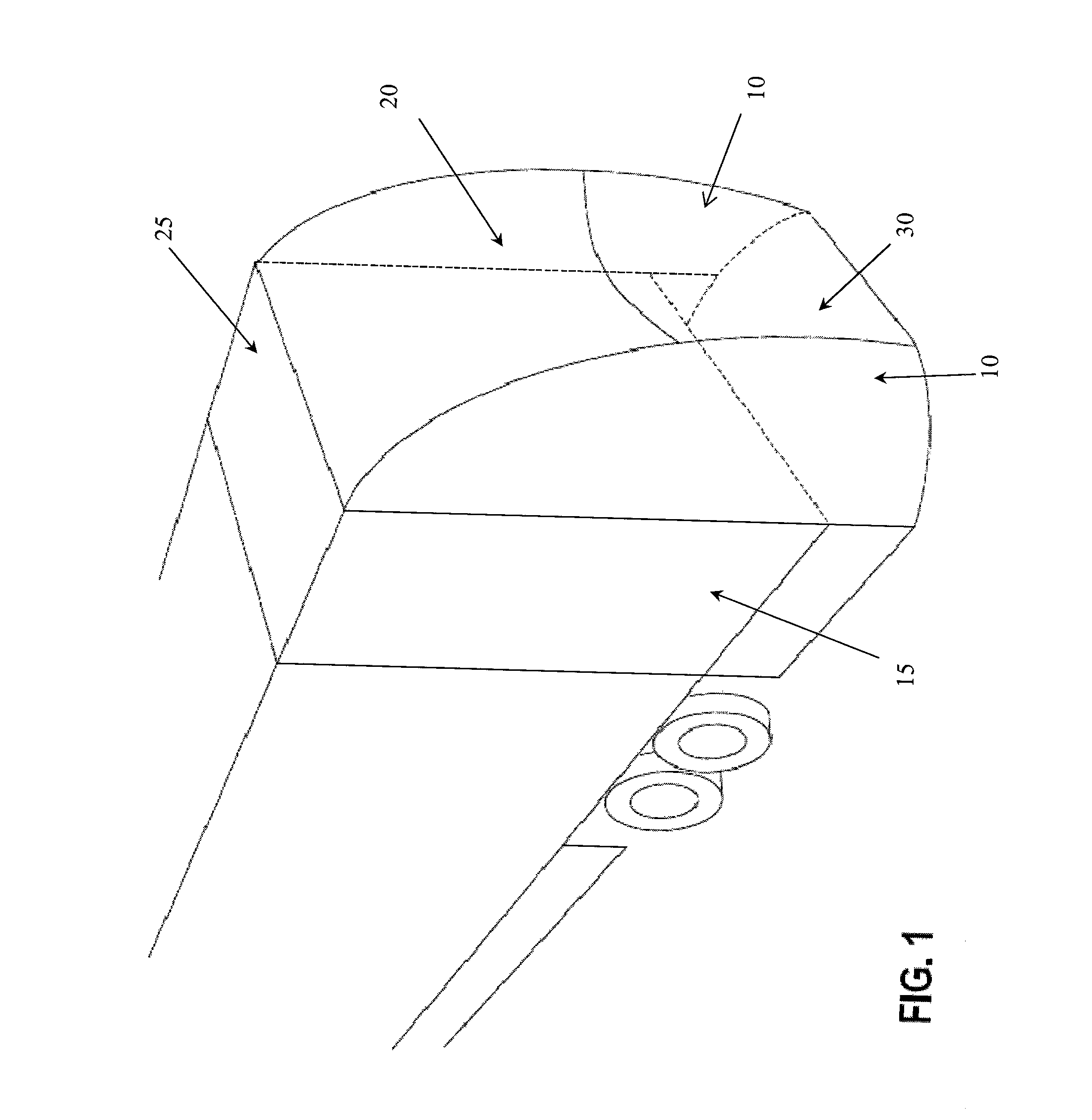
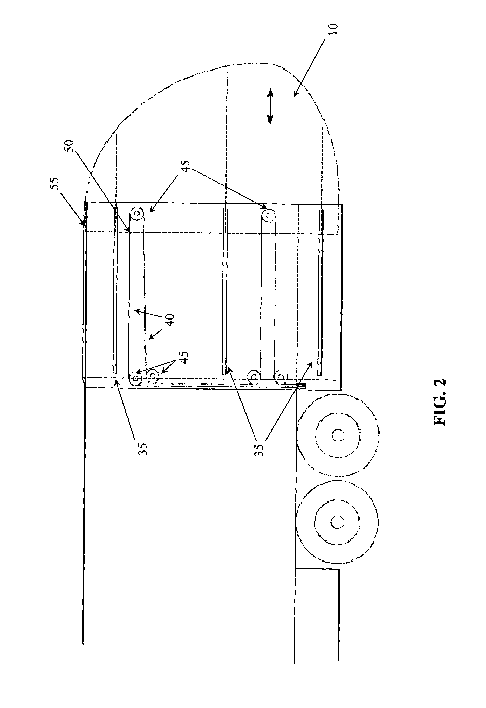
[0041]FIG. 1 illustrates a perspective view in which three aerodynamic panels deployed at the rear of a vehicle. There are two side panels (10) and an upper central panel (20). A fourth, optional panel (30), can also be used in the present invention. The panels are attached to each other at the upper front corners, the details of which are described below. The size of the panels can vary according to the size of the vehicle, and according to the aerodynamic design. Furthermore, the shape of each panel can be varied, so long as the combination of all panels provides an aerodynamic design to the rear of the vehicle. In addition, the length of the central panel can vary, so long as an aerodynamic design is maintained at the rear of the truck. The panels are constructed of flexible, li...


PUM


Abstract

An apparatus for reducing drag on a transport vehicle, which comprises retractable aerodynamic panels for deployment at the rear of the vehicle, behind the cabin, or both. When these panels are deployed, they provide an aerodynamic design, thereby reducing drag and turbulence as the vehicle travels, for example, down a highway, which in turn, reduces energy costs associated with transportation. When not in use, the panels retract adjacent to the planar surfaces of the vehicle (for example, the sides, top and bottom surfaces). The retracted panels are housed either on the outside surface of the vehicle; the inside surface of the vehicle, or within the walls of the vehicle. The retracted position of the panels allows for easy unloading of cargo from the rear of the vehicle when it is docked.

Description

FIELD OF THE INVENTION[0001]The present invention relates to a drag-reducing device for use with vehicles having surfaces that lack streamlining. Examples include trucks, trailers, truck-trailer boxes, semi-trailers, and the like. The term ‘vehicle’ is used to describe the all modes of transportation for which the invention can be applied. The device can be mounted at the rear of the vehicle, or, in between a cabin and a following trailer.BACKGROUND OF THE INVENTION[0002]As a vehicle increases its speed, so too does the amount of aerodynamic drag, which in turn, increases the amount of fuel consumption required for transport. This inefficiency leads to a direct increase in operating costs. As a result, there have been many efforts to reduce aerodynamic drag, particularly on transport vehicles which are not sufficiently streamlined to minimize aerodynamic drag.[0003]In particular, transport vehicles, such as trucks, are susceptible to aerodynamic drag, due to the shape of the cabin a...

Claims


Application Information

Patent Timeline
Patent Type & Authority Patents(United States)
IPC IPC(8): B62D35/00
CPCB61D17/02B61D17/06B62D35/001Y02T30/32Y02T30/00Y02T10/82
Inventor VISENTIN, FRANK
Owner VISENTIN FRANK
Why Eureka
Try Eureka