Printing apparatus

a printing apparatus and printing technology, applied in printing, other printing apparatus, etc., can solve the problems of poor accuracy, skew sometimes occurring during the conveyance of sheets,

Inactive Publication Date: 2014-03-18
CANON KK
View PDF24 Cites 10 Cited by
  • Summary
  • Abstract
  • Description
  • Claims
  • Application Information

AI Technical Summary

Benefits of technology

[0007]The present invention has been made based on recognition of the above-mentioned problem. An advantage of the present invention is therefore the provision of a method of enabling measurement of the skew of the skew component during sheet conveyance by the use of a direct sensor.
[0008]According to the present invention there is provided a printing apparatus, comprising a conveying unit for moving a sheet in a first direction, a printing unit for performing printing onto the sheet, a sensor unit which is arranged to detect a surface of the sheet conveyed by the conveying unit, for measuring a moving state of the sheet, and a control unit, wherein the control unit is arranged to obtain information on the skew state of the moving sheet based on results of measurement regarding the moving state of the sheet, the sensor unit being arranged to perform the measurement at a first measurement position and a second measurement position which are distinct from each other in a second direction intersecting the first direction.
[0009]Further features of the present invention will become apparent from the following

Problems solved by technology

However, skew sometimes occurs during conveyance of a sheet due to poor accuracy of manufacture of one or more rollers within a conveying unit or jamming.
The skewing of a sheet during conveyance causes a conveyance error containing a skew component in which the sheet under conveyance gradually veers from its intended original conveyance direction (straight advance).
This skew is an especially serious problem in the conveyance of a continuous sheet, and can also become a problem in the conveyance of cut sheets.

Method used


Image

  • Printing apparatus
  • Printing apparatus
  • Printing apparatus

Examples


first embodiment

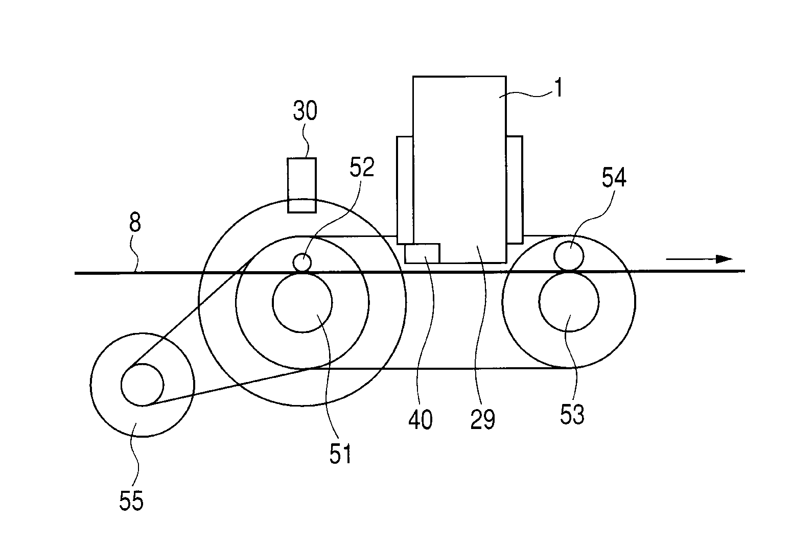
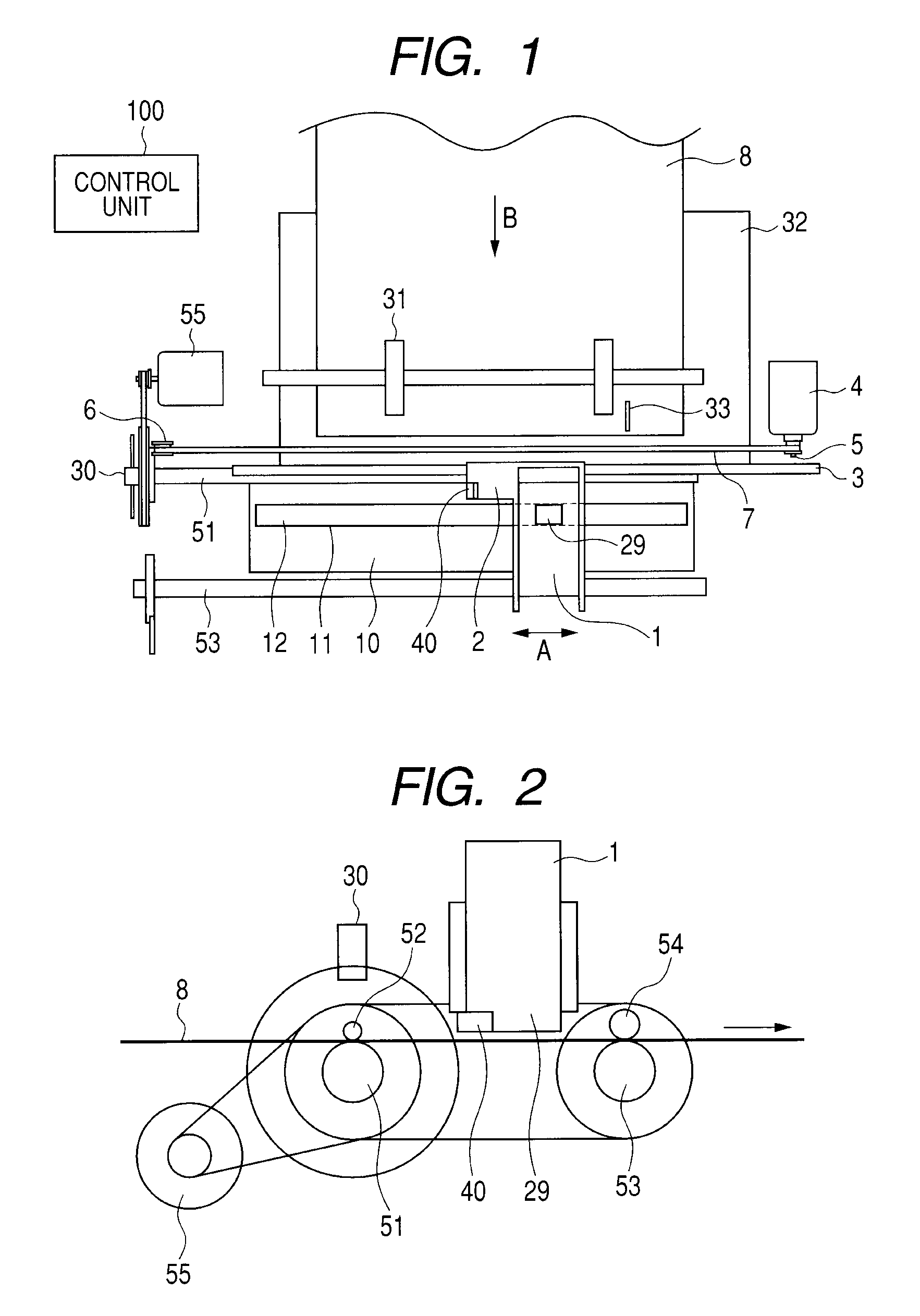
[0022]FIG. 1 is a schematic view illustrating a structure of a printing apparatus according to a first embodiment of the present invention, and FIG. 2 is a cross-sectional view of a main portion of the printing apparatus illustrated in FIG. 1.

[0023]The printing apparatus includes a conveying unit or means for moving a sheet 8 in a sub scanning direction (first direction) and a printing unit or means including a carriage 2 which reciprocates along a main scanning direction (second direction) while holding a print head. In the carriage 2, there is installed a direct-sensor unit or means 40 for directly measuring a moving state of the sheet by optically detecting a surface of the sheet. Other appropriate sensors, such as an RF sensor, can be utilized instead of an optical sensor.

[0024]A head cartridge 1 serving as the print head is detachably installed in the carriage 2. The head cartridge 1 has a discharge port for discharging liquid such as ink in an ink-jetting manner. The head cart...

second embodiment

[0061]Description is made on a second embodiment of the present invention. In this example, as illustrated in FIG. 9, the direct-sensor unit 40 installed in the carriage 2 is positioned on a side nearer the reference side end portion 61 compared with the nozzle rows 29 of the print head. Further, the direct-sensor unit 40 is provided on the further downstream side compared with the groove 11 of the platen 10. Other components are the same as those in the first embodiment. Hereinafter, description is mainly made on differences with the first embodiment.

[0062]After the registration of the leading edge of the sheet, the carriage 2 is moved so that the direct-sensor unit 40 is opposed to the vicinity of the reference side end portion 61 of the sheet 8 (see FIG. 9). The first conveying roller 51 conveys the sheet 8 in the step manner in the sub scanning direction by the predetermined distance corresponding to one band, and the direct-sensor unit 40 performs first measurement at the first...


PUM


Abstract

Provided is a printing apparatus including a sensor unit for measuring a moving state of a sheet by optically detecting a surface of the sheet conveyed by a conveying unit. The sensor unit measures and compares the moving states of the sheet at a first measurement position and a second measurement position which are distinct from each other in a main scanning direction, to thereby obtain information on a skew state of a skew component of the moving sheet.

Description

BACKGROUND OF THE INVENTION[0001]1. Field of the Invention[0002]The present invention relates to a printing apparatus which conveys a sheet, and forms an image on the sheet.[0003]2. Description of the Related Art[0004]In order to realize formation of a high-grade image by a printing apparatus, a sheet-like printing medium (simply refereed to as “sheet” in this specification) is required to be conveyed with a high degree of accuracy.[0005]Recently, in order to improve accuracy in conveyance control, a direct sensor which performs direct detection of the amount of movement of the sheet has been being realized. The direct detection is conducted by imaging a surface of the sheet so as to perform image processing. For example, U.S. Pat. No. 7,104,710 discloses a technology for performing the conveyance control using a direct sensor. In an apparatus disclosed in the above-mentioned U.S. patent, the direct sensor is provided on a carriage in which a print head is installed, or at a positio...

Claims


Application Information

Patent Timeline
Patent Type & Authority Patents(United States)
IPC IPC(8): B41J29/393B41J29/38
CPCB41J11/46B41J11/0095
Inventor SUZUKI, YOSHIAKIKAWAKAMI, KAZUHISASHIGENO, KENJIAOKI, NORIYUKIKANOME, YUJIYAMAMOTO, KOSUKETSUKUDA, MASAKAZUUCHIDA, HARUOSAITO, HIROYUKI
Owner CANON KK
Why Eureka
Try Eureka