
Safe and arm explosive train
a technology of explosive train and safe, which is applied in the field of safe and arm devices, can solve the problems of special challenges in the manufacture of pyrotechnic charges for miniaturized s&a devices such as mems-type systems
- Summary
- Abstract
- Description
- Claims
- Application Information
AI Technical Summary
Benefits of technology
Problems solved by technology
Method used
Image

Examples
Embodiment Construction
[0017]In a device implementing the present invention, a transfer charge connecting between an input charge, such as an initiator or a lead and the output charge of a safe and arm (S&A) device is mechanically controlled to either bring about the detonation train to an interrupted (safe) or to a sequence enabled (armed) state. The interruption of the detonation train prevents the device from activating the output charge.
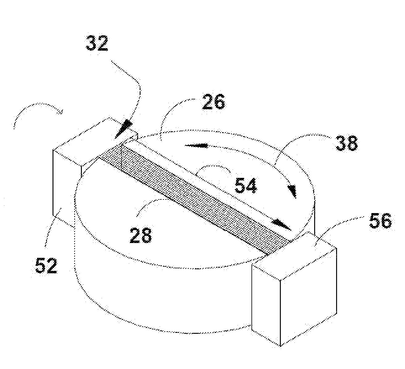
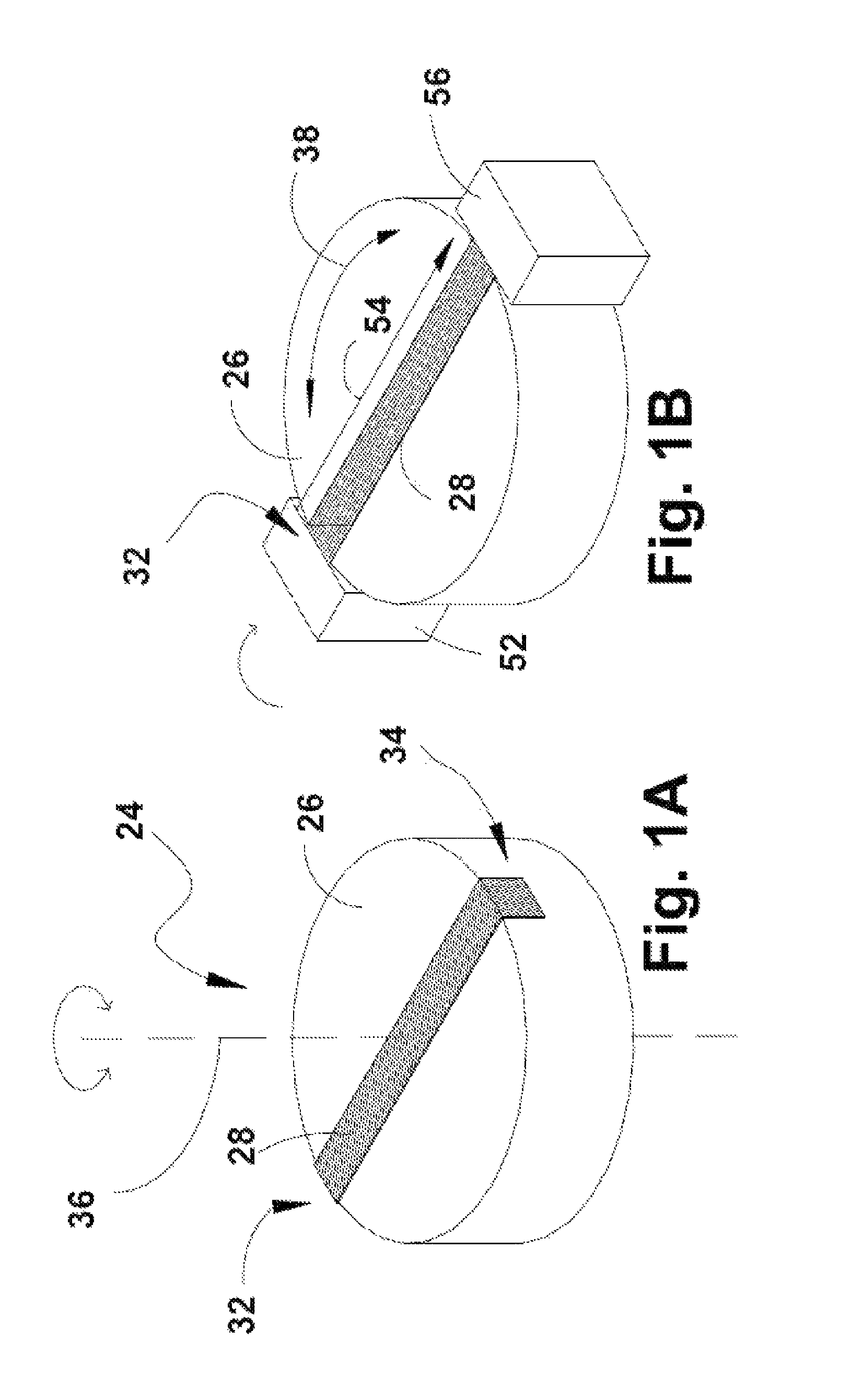
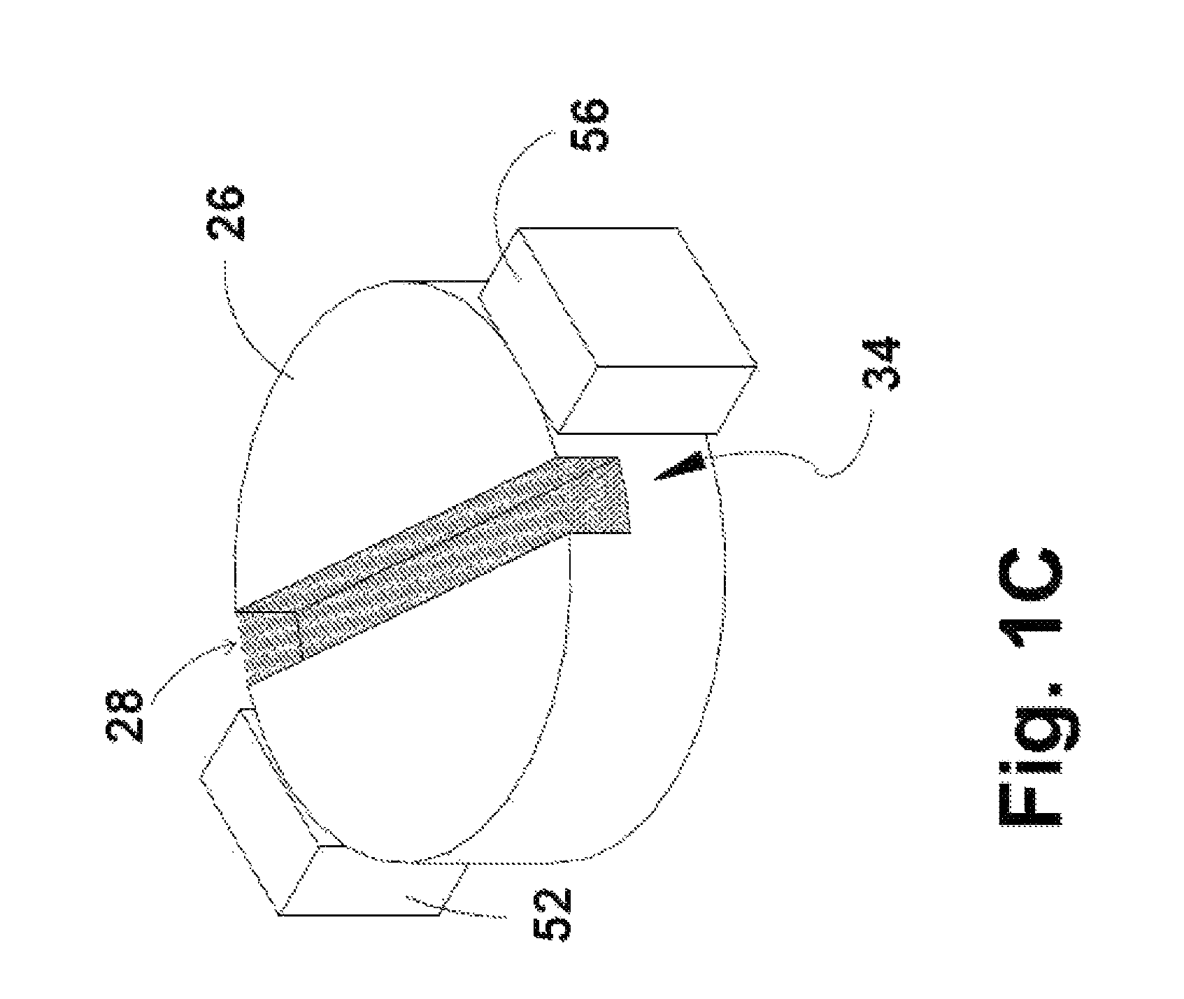
[0018]Referring first to FIG. 1A-C, there is shown a part of a mechanical interruptive transfer assembly, in which a rotatable silicon based transfer charge carrier (TCC) 24 is maintained in either one of two states. First, in FIG. 1A, a schematic description of the rotatable transfer charge carrier (TCC) 24 is shown, detached from its functional environment. Disc 26 is traversed by an explosive porous passage (referred to hereinafter as EPP) 28 which is a defined volume within the silicon based TCC, having a porous structure, constituting a continuous channel from inp...
PUM
 Abstract
Description
Claims
Application Information