Armor mounting system

a technology for armor and mounting brackets, applied in the field of armor mounting brackets, can solve the problems of vehicle difficulty and need for armor replacement, and achieve the effect of reducing the ballistic window of armor

Active Publication Date: 2014-06-24
2040422 ONTARIO
View PDF18 Cites 11 Cited by
  • Summary
  • Abstract
  • Description
  • Claims
  • Application Information

AI Technical Summary

Benefits of technology

[0005]In one aspect of the invention, there is provided armor mounted to a structure by a mounting system, the armor comprising an anti-penetration layer having a front face uninterrupted by the mounting system to thereby reduce ballistic window of the armor.
[0015]The natures of the adapter and the means for rigidly engaging the adapter with the base may differ depending on the type of armor. Adapters may be laminated or placed within the armor between front and rear faces of the armor. Lamination of the adapter into composite armor advantageously does not require holes to be cut into the front face of armor panels, thereby increasing coverage area and ballistic effectiveness. Engagement of the adapter with the base occurs at the rear face of the armor so that the front face presents a generally smooth surface. Any number of adapters may be used with a single armor plate, however, it is advantageous to have enough adapters to securely mount the armor plate to the structure while not having so many that the integrity of the armor is unduly compromised. The appropriate number of adapters is influenced greatly by the size of the armor plate. Advantageously, the same base may be used to mount composite armor or spaced metallic armor, therefore, a single vehicle may be fitted with different kinds of armor at different times thereby increasing the versatility of the vehicle.
[0016]The system advantageously permits retrofitting of previously unarmored structures and / or permits replacement of damaged or obsolete armor. In a retrofitting operation, armor is constructed having adapters engaged therewith. Bases are attached to the structure and then the armor is mounted on the bases by engagement of the adapter with the base. Means for rigidly securing the adapter with the base are employed to ensure that the armor does not fall off the vehicle in operation. If replacement of the armor is desired, the system of the present invention permits easy replacement of the armor without needing to replace the structure. The armor to be replaced is dismounted from the structure by undoing the means for rigidly securing the adapters to the bases and then disengaging the adapters from the bases. New armor may then be mounted on to the existing bases as described above.
[0017]The system advantageously increases ballistic effectiveness by reducing the ballistic window through which projectiles may penetrate. Since the adapters used to mount the armor on a structure are covered by armor, the mounting points no longer create ballistic windows. The system further advantageously renders vehicles stealthier by reducing thermal emissions from the vehicle and by not reflecting radar as readily. The system yet further advantageously permits mounting of composite armor plates on uneven surfaces of structures since the mounting system compensates for the uneven surfaces.

Problems solved by technology

Armored vehicles may be originally manufactured with armor protection integrated into the structure, however, the need to replace the armor due to damage or differing operational requirements of the vehicle is made difficult by such integrated armor.

Method used


Image

  • Armor mounting system
  • Armor mounting system
  • Armor mounting system

Examples


Embodiment Construction

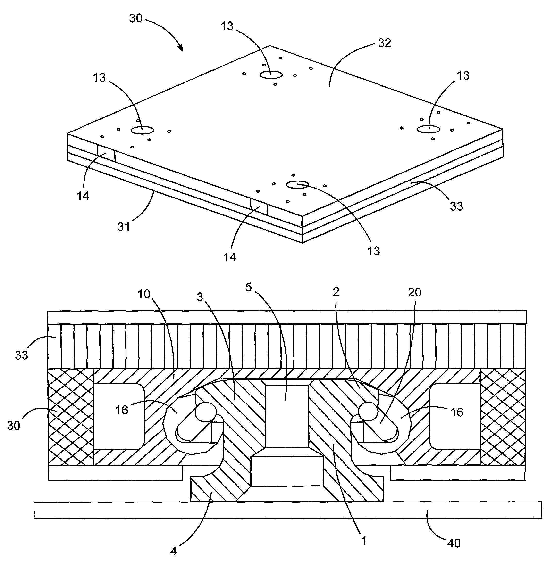
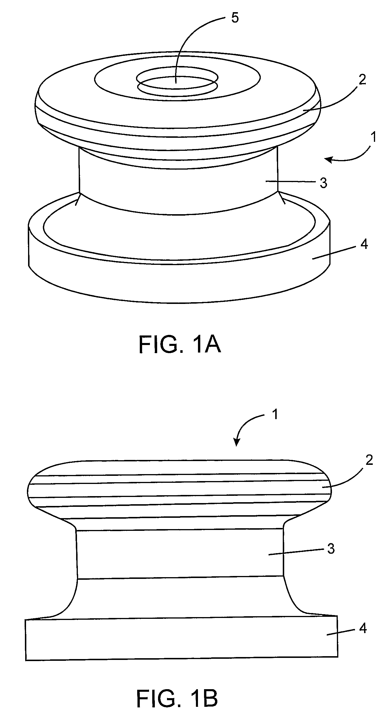
[0035]Referring to FIGS. 1A and 1B, base 1 is generally annular in shape and comprises head portion 2, stem portion 3 having a smaller diameter than head portion 2, and foot portion 4 having a larger diameter than stem portion 3. Threaded bore 5 receives a bolt for securing base 1 to an adapter in connection spaced metallic armor as described below in respect of FIGS. 8-10. Base 1 can be welded to a vehicle hull at foot portion 4.

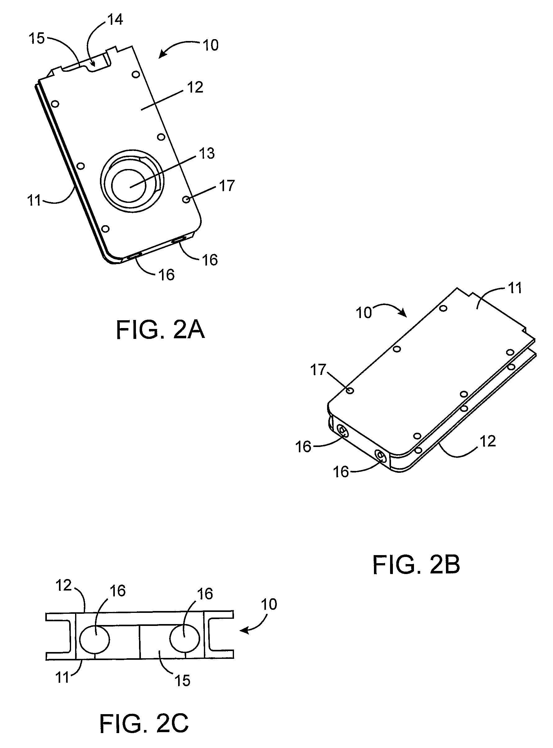
[0036]Referring to FIGS. 2A, 2B and 2C, generally wafer-like adapter 10 suitable for lamination into composite armor comprises front face 11 and rear face 12. Rear face 12 comprises mounting aperture 13 for engagement with the head portion of the base. Pin slot 14 at one end of adapter 10 receives a spring pin in a manner described in connection with FIGS. 4-6 which rigidly secures the head portion of the base within mounting aperture 13 of adapter 10. Pin stop 15 is positioned in pin slot 14 to provide optimal positioning of the spring pin just past top de...


PUM


Abstract

A system for mounting armor to a structure such as a vehicle hull has a base for attachment to the structure, an adapter engaged with the base and with the armor for coupling the base to the armor, and a fastener, for example a pin or a bolt) for rigidly securing the adapter with the base. The system advantageously permits retrofitting of previously unarmored structures and / or permits replacement of damaged or obsolete armor. A kit for retrofitting a structure with armor has a base for attachment to the structure, an adapter for engagement with the base and with the armor for coupling the base to the armor, a fastener for rigidly engaging the adapter with the base, and instructions for mounting the armor on the structure using the base, the adapter and the fastener.

Description

FIELD OF THE INVENTION[0001]This invention relates to a system for mounting armor on a structure, particularly for mounting armor on a vehicle.BACKGROUND OF THE INVENTION[0002]Structures, in particular vehicles, may be provided with ballistic protection by armor. Armored vehicles may be originally manufactured with armor protection integrated into the structure, however, the need to replace the armor due to damage or differing operational requirements of the vehicle is made difficult by such integrated armor. Furthermore, it is often desirable to retrofit previously unarmored vehicles with armor. It is therefore desirable in the art to provide a system for mounting armor on a structure, for example a vehicle, which permits easy replacement of armor and which permits retrofitting of previously unarmored vehicles.[0003]There are a variety of kinds of armor that may be used to protect structures such as vehicles, for example, composite armor and spaced metallic armor. It is desirable t...

Claims


Application Information

Patent Timeline
Patent Type & Authority Patents(United States)
IPC IPC(8): F41H7/00
CPCF41H7/04F41H5/013
Inventor PFISTER, KARL, GERHARD
Owner 2040422 ONTARIO
Why Eureka
Try Eureka