USB connector, USB housing, and wireless modem

a technology of usb connectors and wireless modems, applied in the field of communication technology, can solve the problems of large space requirements, large thickness of usb connectors, and inability to meet the requirements of modern people, and achieve the effect of reducing the thickness and footprint of usb connectors and making them portabl

Active Publication Date: 2014-09-02
HUAWEI DEVICE CO LTD
View PDF25 Cites 0 Cited by
  • Summary
  • Abstract
  • Description
  • Claims
  • Application Information

AI Technical Summary

Benefits of technology

[0006]Embodiments of the present invention provide a USB connector, a USB housing, and a wireless modem, which is capable for reducing the thickness and footprint of the USB connector and therefore portable.
[0011]The foregoing description shows that the bottom of the USB housing can be configured to fix the subcard; the cable penetrates the first hole; the rotating shaft assembly penetrates the second hole. This reduces the thickness and footprint of the USB connector and therefore makes the USB connector portable.

Problems solved by technology

During the implementation of the present invention, the inventor finds that common wireless network access card available on the market are generally not portable and fail to meet the requirements of modern people for compact and exquisite electronic products due to the limitations of USB connectors: The USB connectors are thick and require large space.

Method used


Image

  • USB connector, USB housing, and wireless modem
  • USB connector, USB housing, and wireless modem
  • USB connector, USB housing, and wireless modem

Examples


embodiment 1

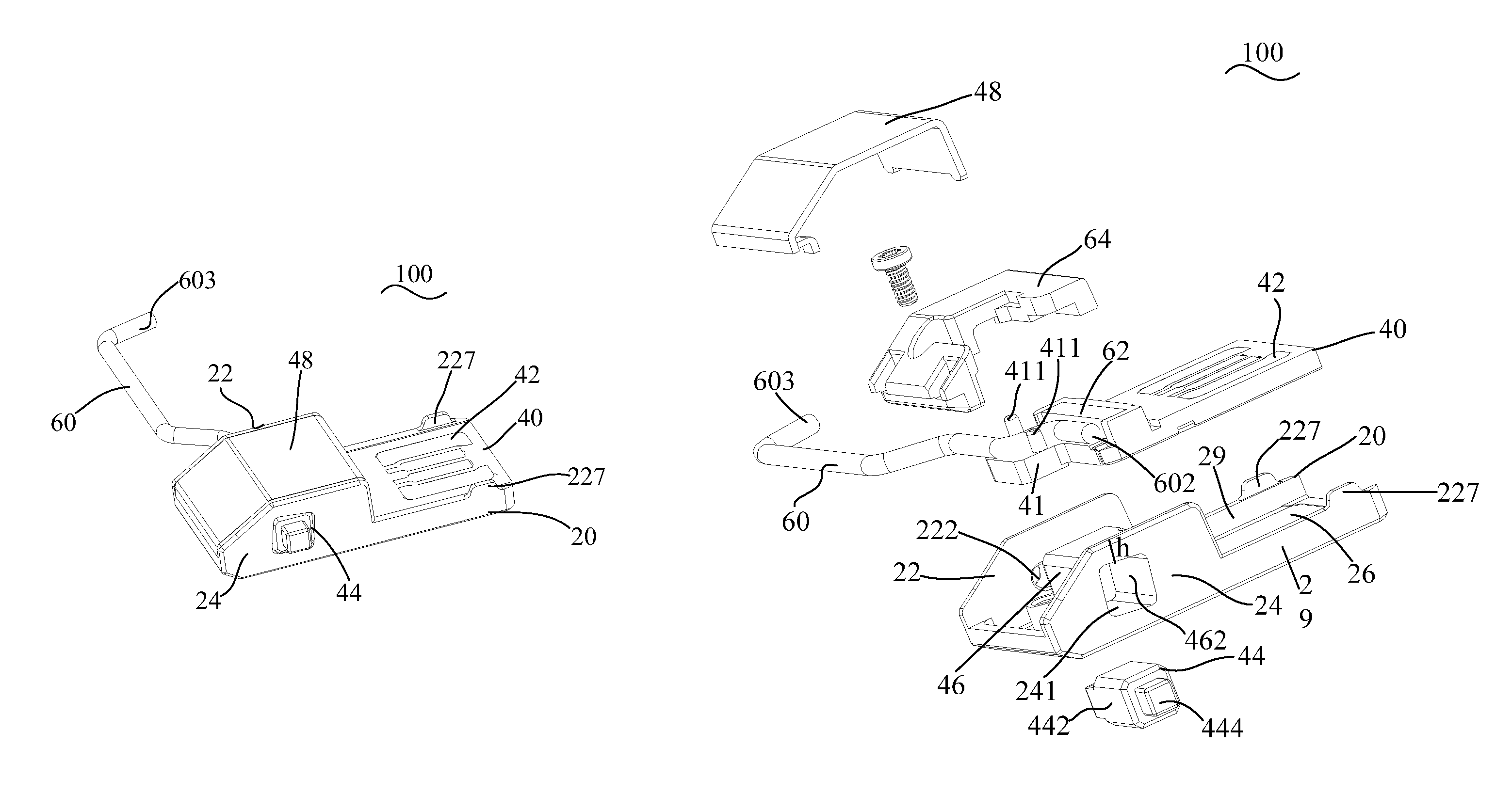
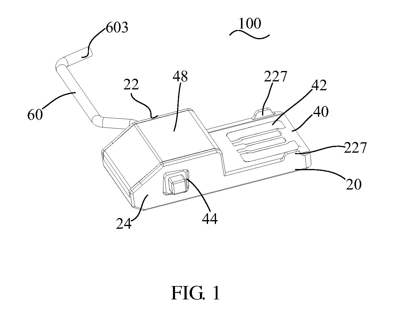
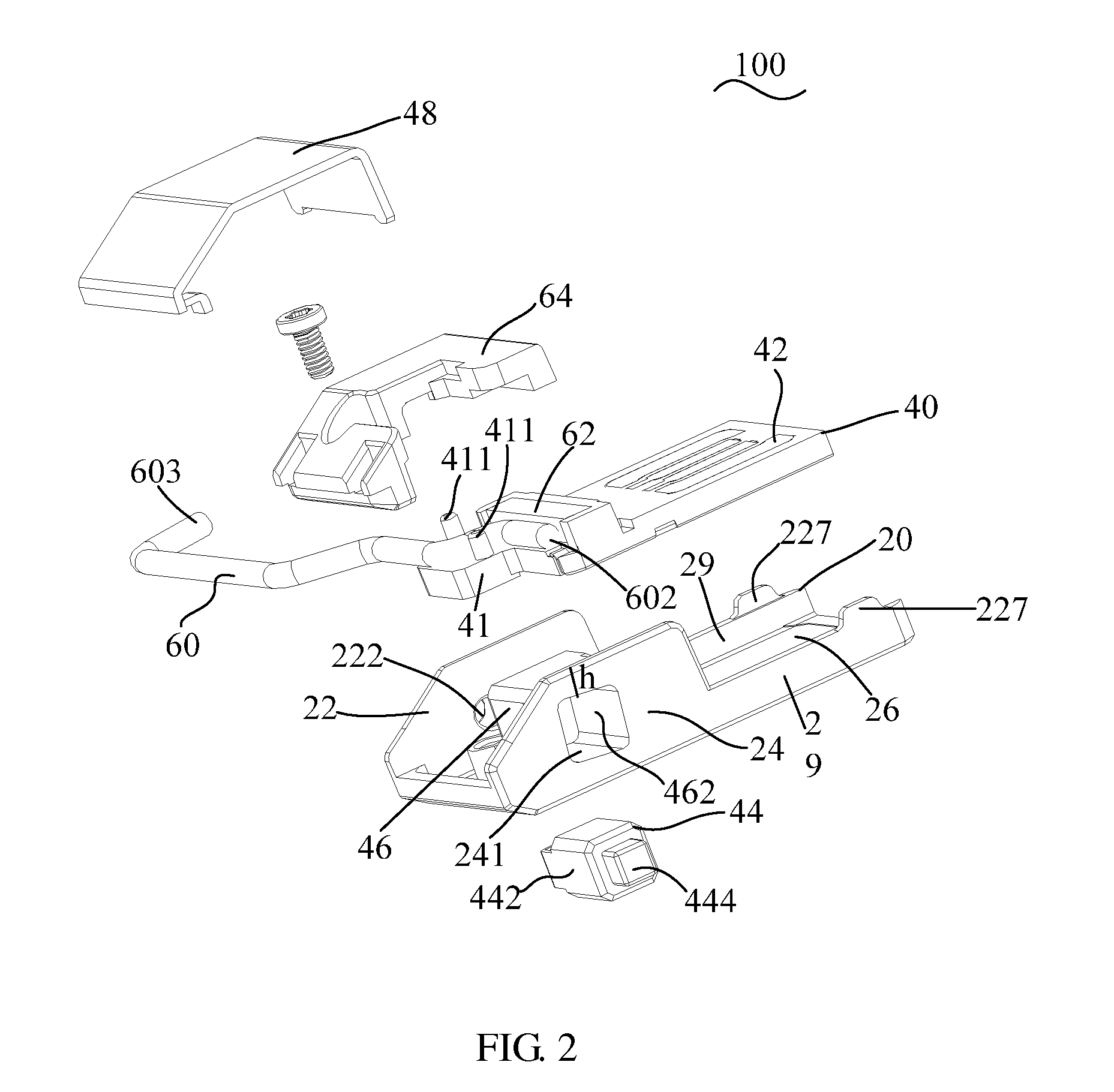
[0026]See FIG. 1 and FIG. 2. FIG. 1 is a three-dimensional schematic structural diagram of a USB connector according to this embodiment of the present invention. FIG. 2 is an exploded diagram of a USB connector according to this embodiment of the present invention.

[0027]A USB connector 100 includes a USB housing 20, a subcard 40, a cable 60, a metal terminal 42, and a rotating shaft assembly 44. The USB housing 20 includes a bottom 26. A first fixing plate 22 and a second fixing plate 24 are respectively disposed on the two opposite sides of the bottom 26. A second hole 241 is disposed on the second fixing plate 24. The subcard 40 is disposed on the bottom 26. The subcard 40, the first fixing plate 22, and the second fixing plate 24 are on a same side of the bottom 26. The metal terminal 42 is partially or fully disposed on the surface of the subcard 40. One end 602 of the cable 60 is connected to the metal terminal 42. The rotating shaft assembly penetrates the second hole 241.

[002...

embodiment 2

[0080]FIG. 7 is a schematic structural diagram of a USB housing according to this embodiment of the present invention. The USB housing 20 includes the bottom 26. The first fixing plate 22 and the second fixing plate 24 are respectively disposed on the two opposite sides of the bottom 26. The first fixing plate 22 and the second fixing plate 24 are on a same end of the bottom 26. The second hole 241 is disposed on the second fixing plate 24. The second hole 241 is used for the penetration of the rotating shaft assembly 44 (see FIG. 2).

[0081]The foregoing description shows that the bottom 26 of the USB housing 20 can be configured to fix the subcard 40; the cable 60 penetrates the first hole 222; the rotating shaft assembly 44 penetrates the second hole 241. This reduces the thickness and occupied space of the USB connector and makes the USB connector portable.

[0082]The first hole 222 is disposed on the first fixing plate 22. The first hole 222 is used for the penetration of the cable...

embodiment 3

[0090]See FIG. 8, FIG. 9, and FIG. 2. FIG. 8 is a schematic structural diagram of a wireless modem according to this embodiment of the present invention. FIG. 9 is an exploded diagram of a wireless modem according to this embodiment of the present invention.

[0091]The wireless modem 600 includes a USB connector 100 and a main body 200. The USB connector 100 includes a USB housing 20, a subcard 40, a cable 60, a metal terminal 42, and rotating shaft assembly 44. The USB housing 20 includes a bottom 26. A first fixing plate 22 and a second fixing plate 26 are respectively disposed on the two opposite sides of the bottom 26. A second hole 241 is disposed on the second fixing plate 24. The subcard 40 is disposed on the bottom 26. The subcard 40, the first fixing plate 22, and the second fixing plate 24 are on a same side of the bottom 26. The metal terminal 42 is partially or fully disposed on the surface of the subcard 40. One end 602 of the cable 60 is connected to the metal terminal 4...


PUM


Abstract

A Universal Serial Bus (USB) connector, a USB housing, and a wireless modem are provided in the embodiments of the present invention. The USB connector includes a USB housing, a subcard, a cable, a metal terminal, and a rotating shaft assembly. The USB housing includes a bottom with a first fixing plate and a second fixing plate respectively disposed on two opposite sides. The second fixing plate is disposed with a second hole. The subcard, the first fixing plate, and the second fixing plate are disposed on a same end of the bottom. The metal terminal is disposed on a surface of the subcard. One end of the cable is connected to the metal terminal. The rotating shaft assembly penetrates the second hole.

Description

[0001]This application claims priority to Chinese Patent Application No. 201010227602.2, filed on Jul. 12, 2010, and Chinese Patent Application No. 201010257477.X, filed on Aug. 13, 2010, both of which are hereby incorporated by reference in their entireties.TECHNICAL FIELD[0002]The present invention relates to the field of communications technology, and more particularly, to a USB connector, a USB housing, and a wireless modem.BACKGROUND[0003]As the mobile communications technologies develop rapidly, data services such as wireless network access become increasingly mature, and portable compact wireless network access terminals, such as wireless modem (including wireless network access card), gain more attention and become more popular.[0004]A legacy wireless network access card can be connected to a computer through a USB connector to provide wireless network access for users.[0005]During the implementation of the present invention, the inventor finds that common wireless network a...

Claims


Application Information

Patent Timeline
Patent Type & Authority Patents(United States)
IPC IPC(8): H01R35/04H01Q1/22H01Q1/24H01R13/15H01R107/00H01R13/44
CPCH01Q1/241H01Q1/2275H01R13/44H01R2107/00H01R35/04
Inventor JIANG, YAMINGZHANG, BINCHEN, PENGSHENG
Owner HUAWEI DEVICE CO LTD
Why Eureka
Try Eureka