Concentric ring gimbal support system

a technology of gimbal and ring, which is applied in the direction of lighting support devices, candle holders, religious equipment, etc., can solve the problems of restricting the user's lateral freedom of movement, affecting the stability of the gimbal, so as to achieve the effect of balancing the weight of tools and quick replacement or substitution of tools or tool components

Active Publication Date: 2014-09-09
BROWN GARRETT W
View PDF48 Cites 23 Cited by
  • Summary
  • Abstract
  • Description
  • Claims
  • Application Information

AI Technical Summary

Benefits of technology

[0008]Illustrative embodiments of the invention are directed to a supporting and orienting apparatus that is angularly agile and can balance the weight of tools, and that preferably permits quick tool or tool component replacement or substitution. Particular embodiments of the invention can be installed around tool-body locations that preclude the use of traditional tool mounts providing rotational freedom.
[0013]The yoke may have a single arm, attached to a ring at one point, or a double arm, in which case each arm is rotatably attached to the ring. The yoke may be modular in construction, thereby allowing various yoke configurations to be used. This flexibility may permit the support structure to be used with a wide variety of tools.

Problems solved by technology

The resulting stresses, particularly from overhead usages, or near-full extension of the arm, are a common cause of work-related shoulder and forearm injuries.
Tool balancers require unobstructed access to overhead, usually fixed, attachment points, which tend to restrict the users lateral freedom of movement.
Also, since the tools usually dangle in a bottom heavy condition from crude attaching eyelets, maintaining a desired angular orientation is impeded.
Even those few balancer installations that connect to annular bearings around the tool body are still restrictive of other axes of freedom.
Furthermore, they can only be installed on tools of a cylindrical construction that permit the unobstructed passage of the inner bearing race along the tool body to the desired point of attachment.
Importantly, such balancers cannot be used at all for work locations that are inaccessible to overhead support, such as underneath cars on assembly lines.
Some may include two or three-axis gimbal attachments to provide angular freedom between the arm and the supported equipment, but these gimbal designs are not appropriate for the majority of tool configurations and / or conditions of use.
Additionally, the center-of-gravity of a given tool is often located within a non-cylindrical section of the tool body, which may be inaccessible to the sliding installation of a bearing of appropriate size.
Conventional gimbals also cannot be conveniently and quickly removed to facilitate the use of the tool in a separate location, or the rapid replacement of the tool with another.

Method used


Image

  • Concentric ring gimbal support system
  • Concentric ring gimbal support system
  • Concentric ring gimbal support system

Examples


Embodiment Construction

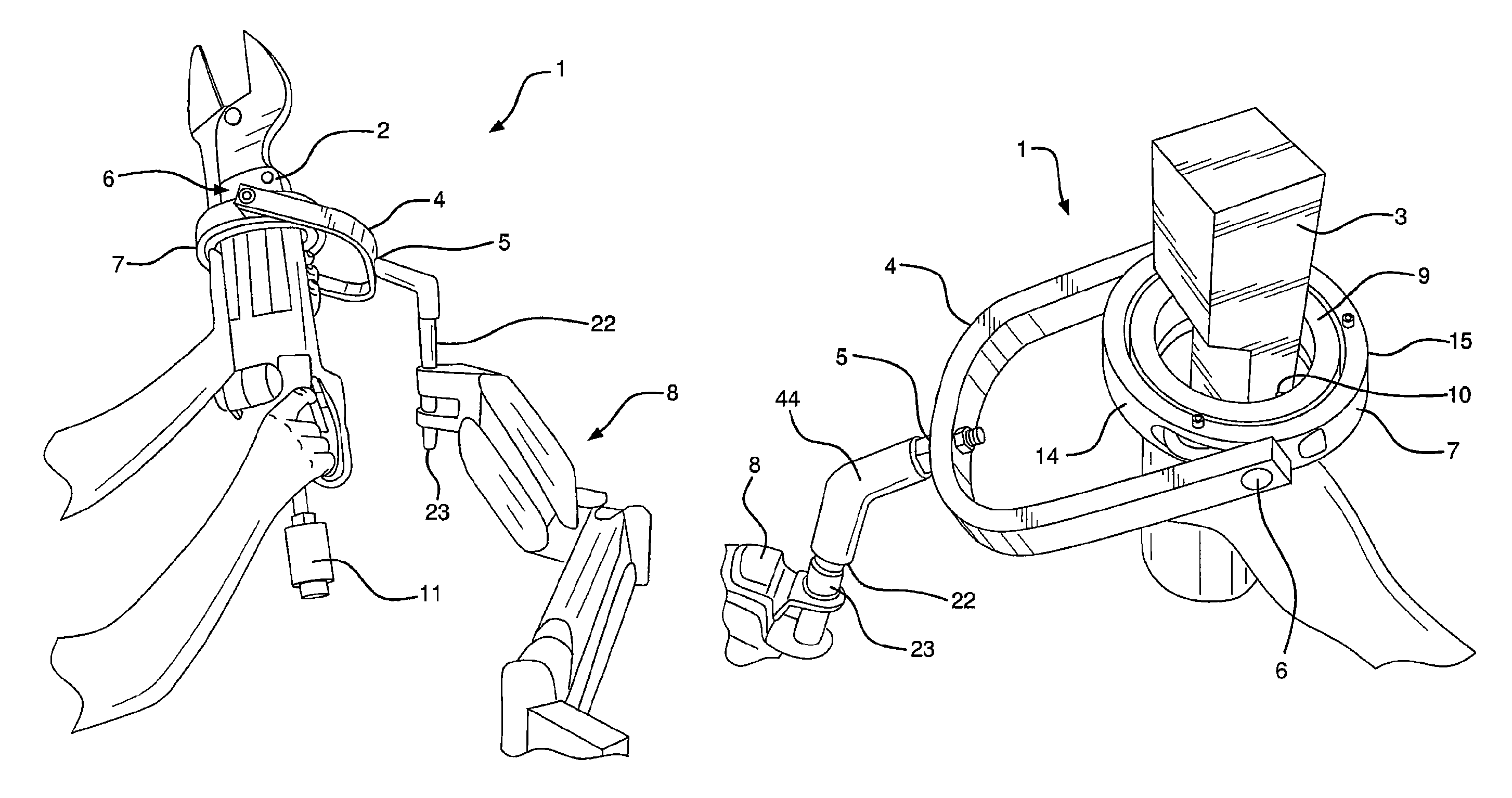
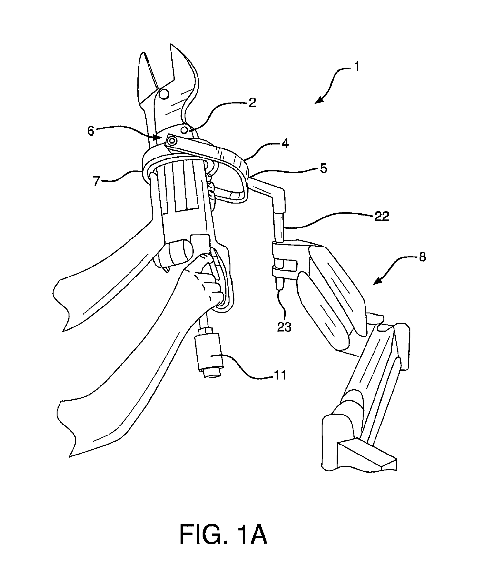
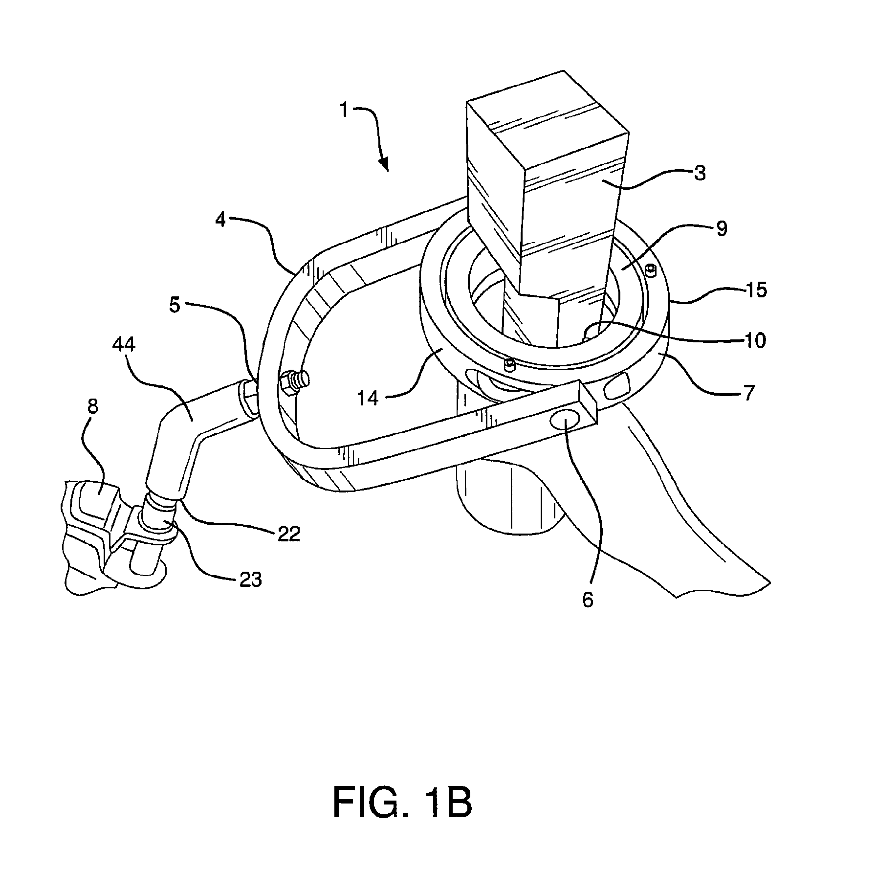
[0043]Illustrative embodiments of the invention offer a support and orienting apparatus that can provide numerous degrees of freedom. Preferably, one or more of the system's elements are modular, sectional, removable and / or capable of disassembly in order to provide mounting flexibility and / or interchangeability, as well uncluttered access to the tool.

[0044]FIG. 1a depicts a tool support system according to an illustrative embodiment of the invention. A ‘squeezer’ rivet tool 2 is shown mounted in a gimbal assembly 1 attached to an articulated support arm 8, shown at nearly its highest position. For many applications it is preferable that the gimbal assembly is removable from the articulated support arm 8 and / or that various parts within the assembly are detachable from one another, particularly in a readily removable manner. Rivet tool 2 is captured at nearly its longitudinal center of balance within gimbal assembly 1. Balancing component 11 provides a balance adjustment so the tool...


PUM

PropertyMeasurementUnit
total diameteraaaaaaaaaa
flange anglesaaaaaaaaaa

Abstract

A tool support system is disclose having a yoke; a plurality of concentric rings having at least one ring pivotally connected to the yoke; a tool fastening mechanism to secure a tool in the support system; and one or more rotation components to permit the tool to rotate within a ring of the support structure. One or more of the concentric rings can be added to the system or can replace one or more concentric rings to accommodate tools of different sizes. The invention includes a method of configuring a support apparatus and a support apparatus kit with various interchangeable parts, and parts that can be built out to varying degrees to permit the support structure to be used on numerous types of tools.

Description

[0001]This application is based on and claims priority to, PCT Patent Application PCT / US2008 / 076331, filed Sep. 13, 2008, entitled Gimbal for Tool Support, which claims priority to U.S. Patent Application 60 / 972,979 , filed Sep. 17, 2007, entitled, Removable Gimbal for Tool Support, both of which are incorporated herein by reference.BACKGROUND OF THE INVENTION[0002]In many industrial and business environments, workers are often required to repetitively lift, position and orient tools, sometimes of significant weight, and deploy them anywhere within the reach of their arms, from low to overhead to extend out in front. The resulting stresses, particularly from overhead usages, or near-full extension of the arm, are a common cause of work-related shoulder and forearm injuries.[0003]Ergonomic equipment supports are known in the art, including ‘tool balancers’ that suspend tools on wires from retractable reels. Tool balancers require unobstructed access to overhead, usually fixed, attach...

Claims


Application Information

Patent Timeline
Patent Type & Authority Patents(United States)
IPC IPC(8): A47F5/05F16M11/00B25B17/00B25H1/00F16M11/04F16M11/12F16M13/04
CPCB25H1/0021F16M11/123F16M13/04F16M11/04F16M2200/068Y10T29/49947
Inventor BROWN, GARRETT W.SACKSTEDER, ANTHONY D.BLACK, MICAHASMANN, DAVID G.
Owner BROWN GARRETT W
Why Eureka
Try Eureka