Vehicle structure

a technology for vehicles and structures, applied in cycle equipment, roofs, transportation and packaging, etc., can solve the problems of deterioration of design flexibility and increase of vehicle weight, and achieve the effect of reducing design flexibility and not increasing vehicle weigh

Active Publication Date: 2015-01-27
MAZDA MOTOR CORP
View PDF21 Cites 14 Cited by
  • Summary
  • Abstract
  • Description
  • Claims
  • Application Information

AI Technical Summary

Benefits of technology

[0008]An object of the present invention is to provide a vehicle structure which can properly hold a passenger's foot at the footrest, without increasing the vehicle weight or deteriorating the design flexibility, even in a case in which the small overlap collision, in which the collision load is directly inputted to the inside of the vehicle compartment from the vehicle side, occurs.
[0009]According to the present invention, there is provided a vehicle structure, comprising a front wheelhouse covering a front wheel, the front wheelhouse comprising a rear face and a slant face which slants forward and inward from an inward end portion, in a vehicle width direction, of the rear face, a footrest, on which a passenger's foot is placed, the footrest being arranged near and on an inward side of the slant face of the front wheelhouse in a plan view of a vehicle, and a gusset connected to the rear face of the front wheelhouse and extending inward from a connection portion thereof to the rear face, wherein an inward end portion, in the vehicle width direction, of the gusset is arranged in the vicinity of a front-side portion of the footrest such that the footrest is restrained from moving forward by contacting the inward end portion of the gusset in a vehicle collision.
[0010]According to the present invention, in the case in which the vehicle has the small overlap collision, the footrest comes to contact the inward end portion of the gusset, so that the footrest can be restrained from moving forward, without increasing the vehicle weight or deteriorating the design flexibility. Accordingly, the direction (position) of the foot can be controlled appropriately, so that the foot can be properly held at the footrest.
[0011]According to an embodiment of the present invention, the footrest is configured to extend upward and forward, and the inward end portion of the gusset is arranged in the vicinity of an upper portion of the front-side portion of the footrest such that the footrest is restrained from moving forward by contacting the upper portion of the inward end portion of the gusset in the vehicle collision. Thereby, the moving of a front end portion of the footrest can be effectively restrained by the inward end portion of the gusset in the small overlap collision. Accordingly, the effect that the foot is properly held at the footrest can be further promoted.
[0012]According to another embodiment of the present invention, a hinge pillar which has a closed cross section extending in a vehicle vertical direction is arranged on an outward side, in the vehicle width direction, of the front wheelhouse, the hinge pillar is connected to an outward end portion, in the vehicle width direction, of the front wheelhouse, and the gusset is connected to the hinge pillar and the front wheelhouse such that the gusset extends over a connection portion of the hinge pillar to the front wheelhouse. Thereby, the gusset is supported at the hinge pillar having the closed cross section extending in the vehicle vertical direction which is not relatively deformable. Accordingly, the moving of the gusset can be surely restrained even if the small overlap collision occurs, so that the effect that the foot is properly held at the footrest can be further promoted.
[0013]According to another embodiment of the present invention, the footrest has a recess portion which is recessed inward in the vehicle width direction, and the inward end portion of the gusset has a shape which matches the recess portion of the footrest. Thereby, when the footrest contacts the inward end portion of the gusset in the small overlap collision, the inward end portion of the gusset comes to engage with the recess portion of the footrest appropriately. Accordingly, the footrest can be surely restrained from moving forward.

Problems solved by technology

Conventionally, there has been a problem about a collision mode in which a collision load is directly inputted to the inside of a vehicle compartment from a vehicle side, without crushing of front side frames extending in a vehicle longitudinal direction at right-and-left both ends of a vehicle front portion, and a bumper reinforcement interconnecting respective front end portions of the right-and-left front side frames.
Consequently, there is a problem in that the vehicle weight may increase or the design flexibility may deteriorate.
The technology disclosed in the above-described patent document, however, merely assumes the case in which the impact load is inputted from a vehicle front due to a head-on collision of the vehicle with the obstacle, this patent document discloses nothing about countermeasures against the case in which the collision load is directly inputted to the inside of the vehicle compartment from the vehicle side when the small overlap collision occurs.

Method used


Image

  • Vehicle structure
  • Vehicle structure
  • Vehicle structure

Examples


Embodiment Construction

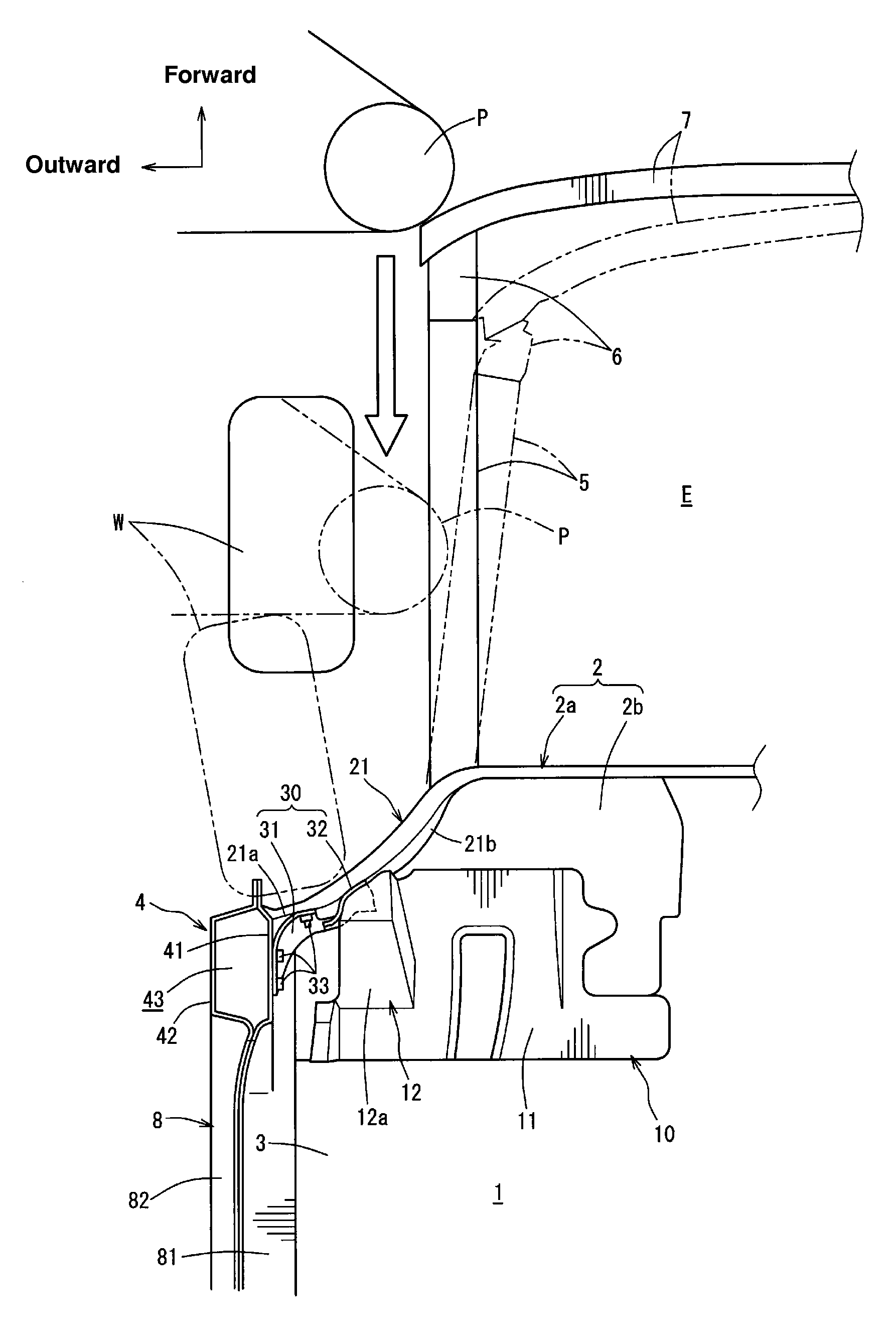
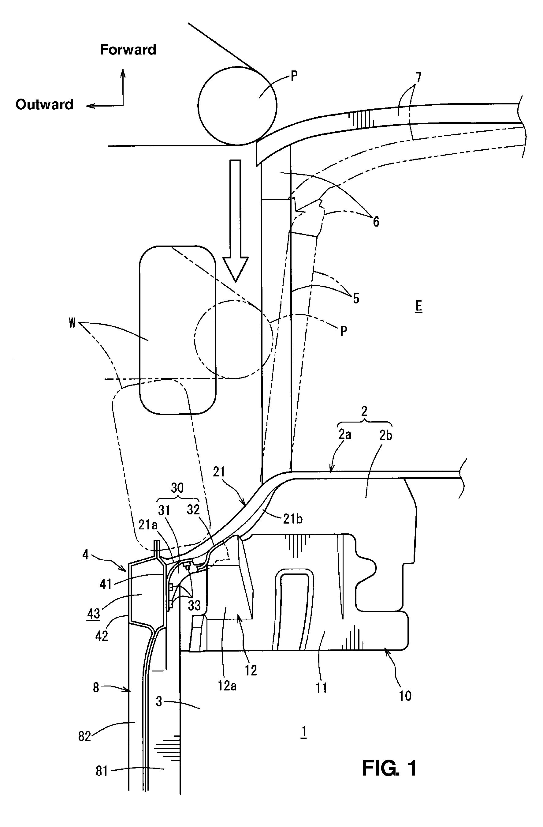
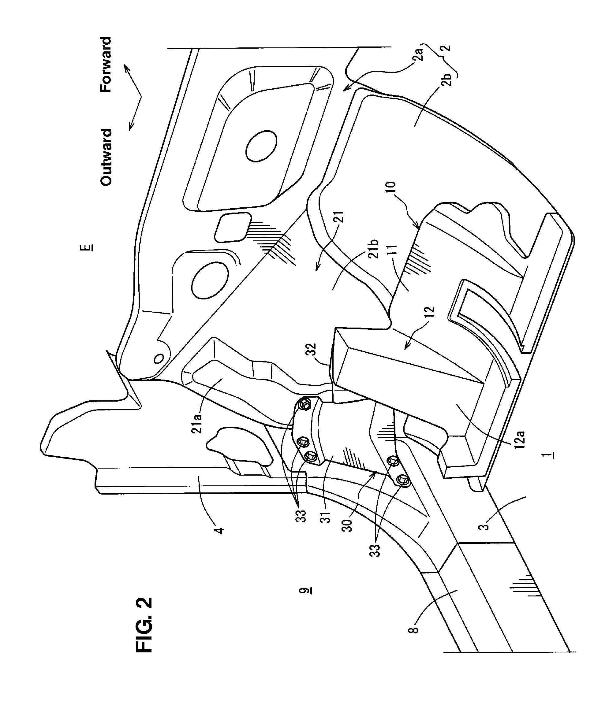
[0021]Hereinafter, a preferred embodiment of the present invention will be described accompanying the drawings. FIG. 1 is a plan view showing a vehicle structure according to an embodiment of the present invention, FIG. 2 is a perspective view of the vehicle structure of FIG. 1, when viewed from a vehicle compartment, FIG. 3 is an elevation view of a gusset and its surrounding portion, when viewed from a vehicle rear, FIG. 4 is a side view of the gusset and a footrest, when viewed from a vehicle side, and FIG. 5 is a sectional view taken along line A-A of FIG. 4.

[0022]As shown in FIGS. 1 and 2, the vehicle according to the present embodiment comprises a dash panel 2 at its front portion, and an engine room E and a vehicle compartment 1 are partitioned from each other by the dash panel 2 which constitutes a front wall portion of the vehicle compartment 1.

[0023]The dash panel 2 is comprised of a dash panel upper 2a which extends vertically and a dash panel lower 2b which extends downw...


PUM


Abstract

A vehicle structure, comprising a front wheelhouse covering a front wheel, the front wheel comprising a rear face and a slant face which slants forward and inward from an inward end portion, in a vehicle width direction, of the rear face, a footrest, on which a passenger's foot is placed, the footrest being arranged near and on an inward side of the slant face of the front wheelhouse in a plan view of a vehicle, and a gusset connected to the rear face of the front wheelhouse and extending inward from a connection portion thereof to the rear face, wherein an inward end portion, in the vehicle width direction, of the gusset is arranged in the vicinity of a front-side portion of the footrest such that the footrest is restrained from moving forward by contacting the inward end portion of the gusset in a vehicle collision.

Description

BACKGROUND OF THE INVENTION[0001]The present invention relates to a vehicle structure in which a footrest on which a driver's foot is placed is arranged near and on an inward side, in a vehicle width direction, of a slant face of a front wheelhouse in a plan view of a vehicle.[0002]Conventionally, there has been a problem about a collision mode in which a collision load is directly inputted to the inside of a vehicle compartment from a vehicle side, without crushing of front side frames extending in a vehicle longitudinal direction at right-and-left both ends of a vehicle front portion, and a bumper reinforcement interconnecting respective front end portions of the right-and-left front side frames.[0003]This collision mode is called a “small overlap collision”, which may occur in a case in which the vehicle front portion collides with an obstacle having a small width in the vehicle width direction, such as a pole, at its one-side end portion.[0004]The above-described small overlap c...

Claims


Application Information

Patent Timeline
Patent Type & Authority Patents(United States)
IPC IPC(8): B60N3/06B62D21/15B62D25/08
CPCB62D25/08B62D21/152B62D25/082B60N3/06
Inventor OBAYASHI, AKIHIROFUKUDA, MASANORIMIYAHARA, RYOHEIMITSUNARI, TOMOSHI
Owner MAZDA MOTOR CORP
Why Eureka
Try Eureka