Controlled power dissipation in a switch path in a lighting system

a technology of switching power converter and control path, which is applied in the field of electronic devices, can solve the problems of flicker and instability, all switching power converters have some inherent power losses, and affect the lighting system, so as to reduce the power dissipation of the boost switch and increase the energy dissipation

Inactive Publication Date: 2015-07-14
SIGNIFY HLDG BV
View PDF122 Cites 48 Cited by
  • Summary
  • Abstract
  • Description
  • Claims
  • Application Information

AI Technical Summary

Benefits of technology

[0018]In another embodiment of the present invention, an apparatus includes a controller configured to control a boost switch in a switching power converter of a phase cut compatible, dimmable lighting system. The controller is configured to control the boost switch in an efficient mode and a power dissipation mode. In the efficient mode, the controller is configured to operate the boost switch to minimize power dissipation in the boost switch. In the power dissipation mode the controller is configured to operate the boost switch to increase dissipation of energy in the boost switch relative to any power dissipation in the boost switch during operation in the efficient mode.

Problems solved by technology

All switching power converters have some inherent power losses due to, for example, non-ideal component characteristics.
Premature disconnects can cause problems with the lighting system, such as flicker and instability.
However, circuits are generally designed to minimize inherent power losses, and these inherent power losses are often negligible and, thus, insufficient to dissipate enough power to compensate for the difference between the POWER IN and the POWER OUT+PINH at some POWER OUT levels.

Method used


Image

  • Controlled power dissipation in a switch path in a lighting system
  • Controlled power dissipation in a switch path in a lighting system
  • Controlled power dissipation in a switch path in a lighting system

Examples


Embodiment Construction

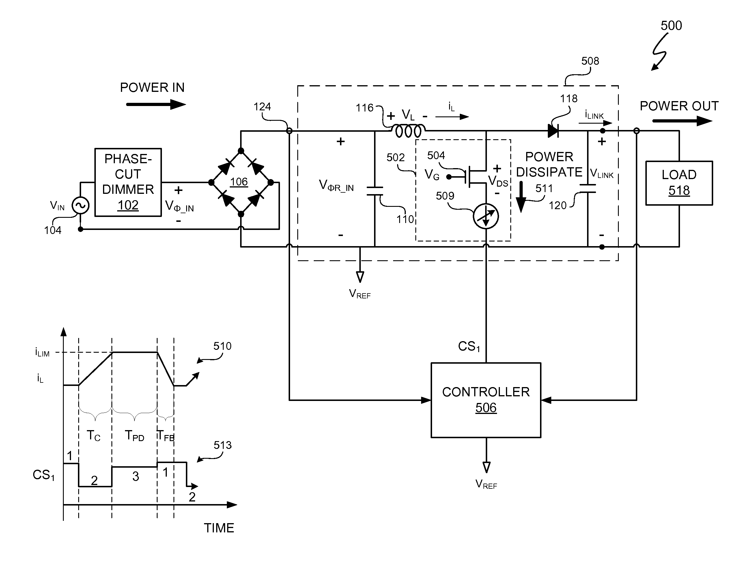
[0038]A lighting system includes one or more methods and systems to control dissipation of excess power in the lighting system when the power into a switching power converter from a leading edge, phase-cut dimmer is greater than the power out of the switching power converter. In at least one embodiment, the lighting system includes a controller that controls dissipation of excess energy in the lighting system to prevent a premature disconnection of the phase-cut dimmer. In at least one embodiment, the controller actively controls power dissipation by generating one or more signals to actively and selectively control power dissipation in the lighting system. By actively and selectively controlling power dissipation in the lighting system, the controller intentionally dissipates power when the power into the lighting system should be greater than the power out to a lamp of the lighting system. However, when the ‘power in’ can equal the ‘power out’ plus any inherent power losses withou...


PUM


Abstract

A lighting system includes one or more methods and systems to control dissipation of excess power in the lighting system when the power into a switching power converter from a leading edge, phase-cut dimmer is greater than the power out of the switching power converter. In at least one embodiment, the lighting system includes a controller that controls dissipation of excess energy in the lighting system to prevent a premature disconnection of the phase-cut dimmer. In at least one embodiment, the controller actively controls power dissipation by generating one or more signals to actively and selectively control power dissipation in the lighting system. By actively and selectively controlling power dissipation in the lighting system, the controller intentionally dissipates power when the power into the lighting system should be greater than the power out to a lamp of the lighting system.

Description

CROSS-REFERENCE TO RELATED APPLICATION[0001]This application claims the benefit under 35 U.S.C. §119(e) and 37 C.F.R. §1.78 of U.S. Provisional Application No. 61 / 410,168, filed on Nov. 4, 2010, and is incorporated by reference in its entirety.BACKGROUND OF THE INVENTION[0002]1. Field of the Invention[0003]The present invention relates in general to the field of electronics, and more specifically to a method and system for controlling energy dissipation in a switching power converter.[0004]2. Description of the Related Art[0005]Switching power converters convert power received from a power source, such as a voltage supply, into power suitable for a load. The power received from the voltage supply is referred to as “POWER IN”, and the power provided to the load is referred to as “POWER OUT”. All switching power converters have some inherent power losses due to, for example, non-ideal component characteristics. Such inherent power losses tend to be minimized so as to increase the effi...

Claims


Application Information

Patent Timeline
Patent Type & Authority Patents(United States)
IPC IPC(8): H05B33/08H02M1/42H05B41/24H05B41/292H05B41/34H02M1/00H05B44/00
CPCH05B33/0815H02M1/4225H02M2001/0045H05B41/245H05B41/2928H05B41/34Y02B20/346Y02B70/126Y02B20/30Y02B70/10H05B45/38H05B45/385H05B45/39H02M1/0045
Inventor MELANSON, JOHN L.KING, ERIC J.
Owner SIGNIFY HLDG BV
Why Eureka
Try Eureka