Organic electroluminescence displaying apparatus which suppresses a defective display caused by a leak current at a time when an emission period controlling transistor is off

a display apparatus and electroluminescence technology, applied in static indicating devices, instruments, cathode-ray tube indicators, etc., can solve problems such as defective display, defective display, and defective display, and achieve the effect of suppressing a defective display

Active Publication Date: 2015-12-08
CANON KK +1
View PDF32 Cites 0 Cited by
  • Summary
  • Abstract
  • Description
  • Claims
  • Application Information

AI Technical Summary

Benefits of technology

[0010]In consideration of the above-described conventional problem, the present invention aims to provide an organic EL displaying apparatus which suppresses a defective display caused by a leak current at a time when an emission period controlling transistor is off.
[0012]According to the present invention, the luminance obtained by the leak current at the time when the emission period controlling transistor is off in a non emission period does not become larger than the luminance corresponding to the minimum gradation displaying data in an emission period. Therefore, it is possible to suppress that defective display such as a luminance variation, black floating at the time of the minimum gradation display, or the like occurs.

Problems solved by technology

However, since a current-luminance characteristic of the organic EL element is not linear, a complicated system is necessary to make a gamma characteristic constant between the high-luminance displaying mode and the low-luminance displaying mode.
However, in case of performing driving to control the emission period as disclosed in Japanese Patent Application Laid-Open No. 2003-122301, there is a case where a defective display occurs by a leak current at a time when an emission period controlling transistor is off, for the following reason.
Thus, there is a problem that a defective display such as a luminance variation, black floating at the time of the minimum gradation display, or the like occurs.
Thus, in this constitution, since a leak emission amount to be superposed further increases, the contrast deteriorates.

Method used


Image

  • Organic electroluminescence displaying apparatus which suppresses a defective display caused by a leak current at a time when an emission period controlling transistor is off
  • Organic electroluminescence displaying apparatus which suppresses a defective display caused by a leak current at a time when an emission period controlling transistor is off
  • Organic electroluminescence displaying apparatus which suppresses a defective display caused by a leak current at a time when an emission period controlling transistor is off

Examples


first embodiment

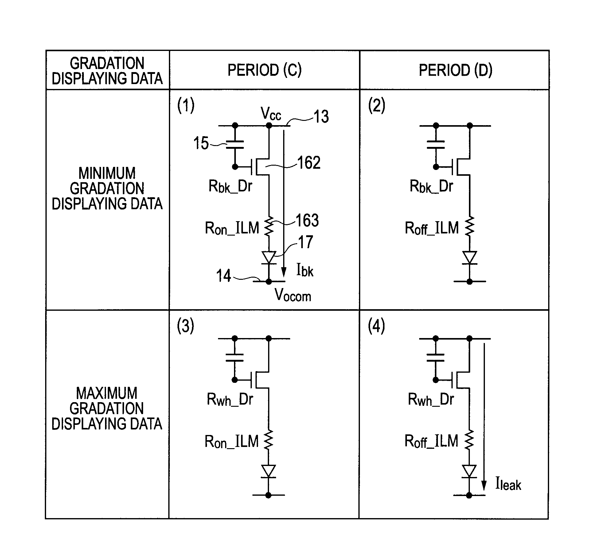
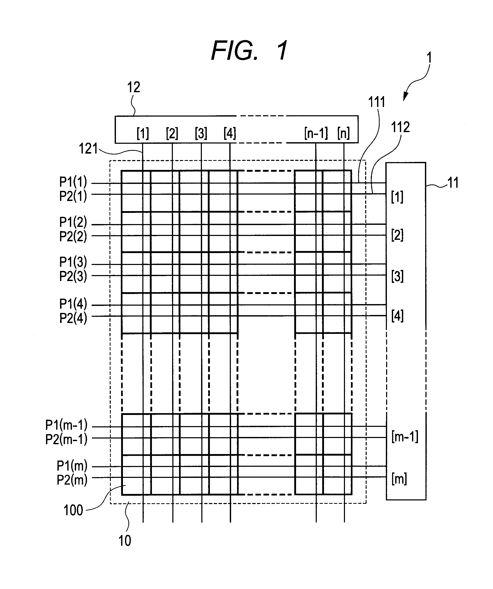
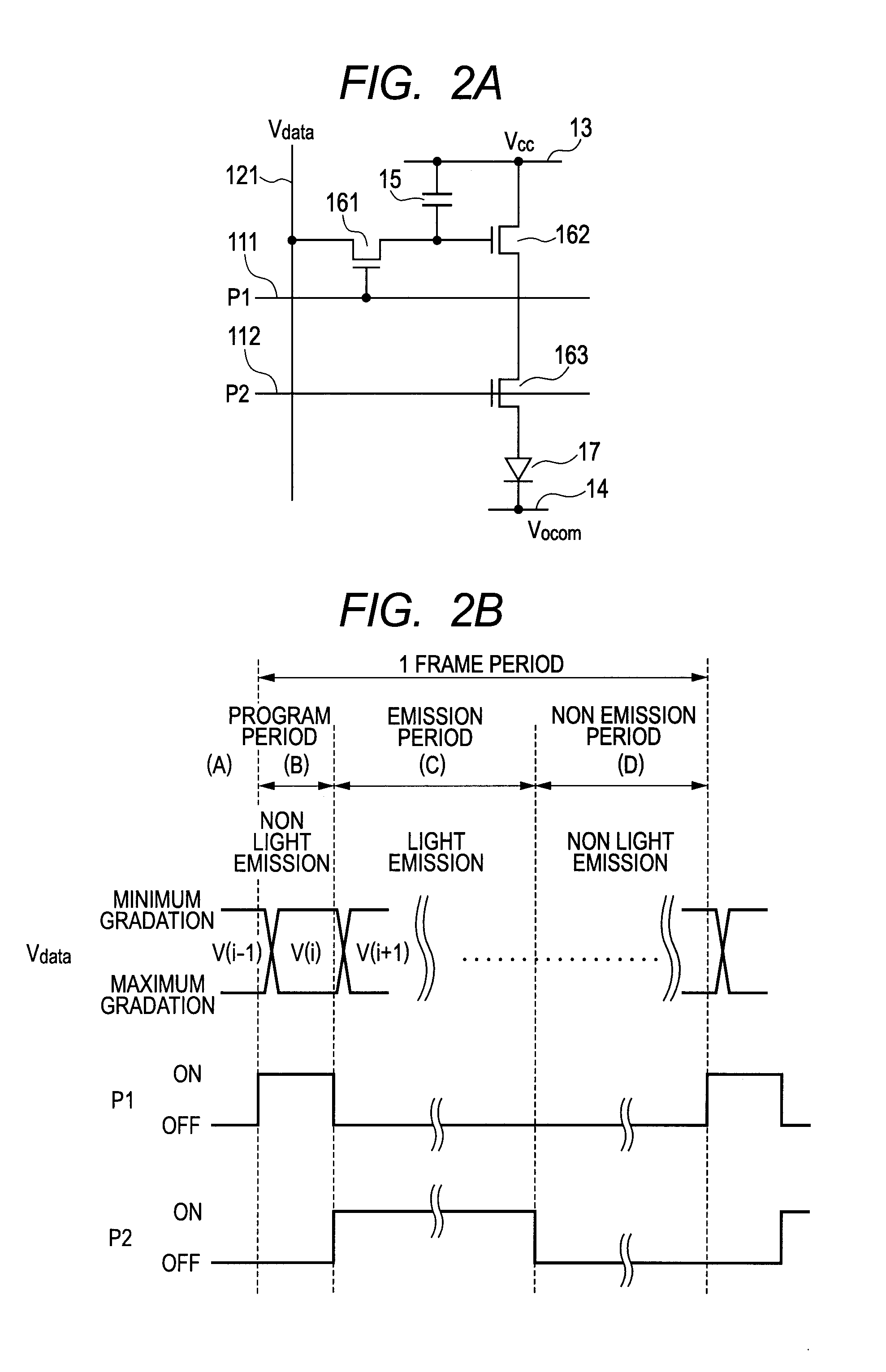
[0026]FIG. 1 is a diagram illustrating a constitution of an organic EL displaying apparatus 1 according to the first embodiment of the present invention. In the present embodiment, the organic EL displaying apparatus 1 has a displaying region 10 in which a plurality of pixels 100 are two-dimensionally arranged in the form of m rows×n columns (m, n are natural numbers). Each of the pixels 100 in the displaying region 10 is a red pixel, a blue pixel or a green pixel, and each pixel has an organic EL element, a driving transistor and an emission period controlling transistor. Here, the driving transistor supplies a current according to potential of the gate electrode to the organic EL element, and the emission period controlling transistor, which is connected between the source electrode or the drain electrode of the driving transistor and the organic EL element, controls light emission of the organic EL element in response to a control signal. Incidentally, the emission period control...

example 1

[0066]A concrete example of the organic EL displaying apparatus 1 according to the first embodiment will be described hereinafter. Here, it should be noted that the present invention is not limited to the following examples. Moreover, it should be noted that the present invention is not limited by the polarities or the sizes of the transistors, the pixel arrangements, the pixel pitches, or the like, used in the following examples.

[0067]In this example, in the pixel circuit illustrated in FIG. 2A, the selecting transistor 161 is an N-type transistor, the driving transistor 162 is a P-type transistor, and the emission period controlling transistor 163 is an N-type transistor.

[0068]In this example, the two-dimensional arrangement of the pixels 100 illustrated in FIG. 1 was set to 480 rows×1920 columns, and the pixel pitches of the pixels 100 in the row direction and the column direction were set to 94.5 μm and 31.5 μm respectively. Further, the pixels 100 were constituted so that pixel...

example 2

[0109]In the organic El displaying apparatus according to the first embodiment, another concrete example different from Example 1 will be described. The organic EL displaying apparatus in this example is the same as the organic EL displaying apparatus in Example 1 except that the polarities of the selecting transistor 161 and the emission period controlling transistor 163 in the pixel are the P type and the contrast is set to 10000:1.

[0110]In the pixel circuit constitution illustrated in FIG. 2A, the selecting transistor 161 is the P-type transistor, the driving transistor 162 is the P-type transistor, and the emission period controlling transistor 163 is the P-type transistor. The current value to be supplied to the organic EL element of each color pixel in the emission period at the maximum gradation displaying time was set to 5×10⁻⁷ A, and the gradation displaying data was set so that the contrast in the case where the proportion t (0162 having its channel length of 24 μm and its...


PUM


Abstract

An organic EL displaying apparatus which suppresses a defective display caused by a leak current at a time when an emission period controlling transistor is off is provided. The organic EL displaying apparatus comprises a plurality of pixels each of which includes an organic EL element, a power supply line, a driving transistor and the emission period controlling transistor, a data line, and a control line. In this apparatus, in a certain one of the pixels, a resistance Roff<sub2>—< / sub2>ILM between source and drain electrodes of the emission period controlling transistor in an off state of the emission period controlling transistor, and a resistance Rbk<sub2>—< / sub2>Dr between source and drain electrodes of the driving transistor in a state that a minimum gradation displaying data voltage has been applied to a gate electrode of the driving transistor satisfy Roff<sub2>—< / sub2>ILM≧Rbk<sub2>—< / sub2>Dr.

Description

BACKGROUND OF THE INVENTION[0001]1. Field of the Invention[0002]The present invention relates to an organic EL (electroluminescence) displaying apparatus.[0003]2. Description of the Related Art[0004]An organic EL displaying apparatus is constituted by arranging pixels each having an organic EL element on a substrate in a matrix form. In each pixel, the organic EL element is connected in series to a transistor for driving the organic EL element (hereinafter, called a driving transistor) and a power supply line for supplying power to the organic EL element. Here, Japanese Patent Application Laid-Open No. 2003-122301 discloses a constitution of achieving a satisfactory moving image displaying characteristic by further providing in series a transistor for controlling an emission period (hereinafter, called an emission period controlling transistor) between the power supply line and the organic EL element.[0005]Further, since the organic EL displaying apparatus is a self-emitting display...

Claims


Application Information

Patent Timeline
Patent Type & Authority Patents(United States)
IPC IPC(8): G09G3/30G09G5/10G09G3/32G09G3/00
CPCG09G3/3233G09G3/006G09G2300/0819G09G2300/0842G09G2300/0861G09G2320/0233G09G2320/0238G09G2320/0295G09G2330/08G09G2330/10G09G3/3258
Inventor TAMAKI, JUNYASATO, NOBUHIKOISEKI, MASAMIIKEDA, KOUJITAMURA, MASAHIROIZUMIDA, TAKESHITOKUDA, NAOKI
Owner CANON KK
Why Eureka
Try Eureka