Abnormality monitoring system and image forming apparatus

a monitoring system and image technology, applied in the direction of electrographic process apparatus, instruments, measurement devices, etc., can solve the problems of complex structure and control system, high-precision control circuit, and high cos

Inactive Publication Date: 2016-03-15
RICOH KK
View PDF2 Cites 4 Cited by
  • Summary
  • Abstract
  • Description
  • Claims
  • Application Information

AI Technical Summary

Problems solved by technology

In a recent electrophotographic image forming apparatus, its structure and control system have been complicated because of the speed-up of functions, high resolution, downsizing of the apparatus, or the like.
When the drives of such a plurality of drive motors are simultaneously controlled and if a single control circuit (CPU) is used for drive control, an expensive and high-precision control circuit has to be used.
However, the image forming apparatus described in Japanese Laid-open Patent Publication No. 2008-047996 is designed only to detect a failure of the fan being an object to be controlled, and therefore abnormality of the harness members H1 to H6 as illustrated in FIG. 6 is not considered.

Method used


Image

  • Abnormality monitoring system and image forming apparatus
  • Abnormality monitoring system and image forming apparatus
  • Abnormality monitoring system and image forming apparatus

Examples


Embodiment Construction

[0022]Exemplary embodiments of the present invention will be explained below with reference to the accompanying drawings, by using an example of a printer dedicated machine as the image forming apparatus on which the abnormality monitoring system is installed.

[0023]As illustrated in FIG. 1, an image forming apparatus 1 on which the abnormality monitoring system according to the present embodiment is installed adopts a tandem intermediate transfer system. An apparatus body 100 of the image forming apparatus 1 includes an exposure device 10, an image forming device 20, an intermediate transfer device 30, a secondary transfer device 40, and a fixing device 50 in the order of an image forming process from its upper side. The apparatus body 100 includes a sheet feeding device 200 in its lower side.

[0024]The sheet feeding device 200 is provided at the lower-side of the apparatus body 100. In the present embodiment, the sheet feeding device 200 has drawer-type sheet feeding cassettes 210 a...


PUM


Abstract

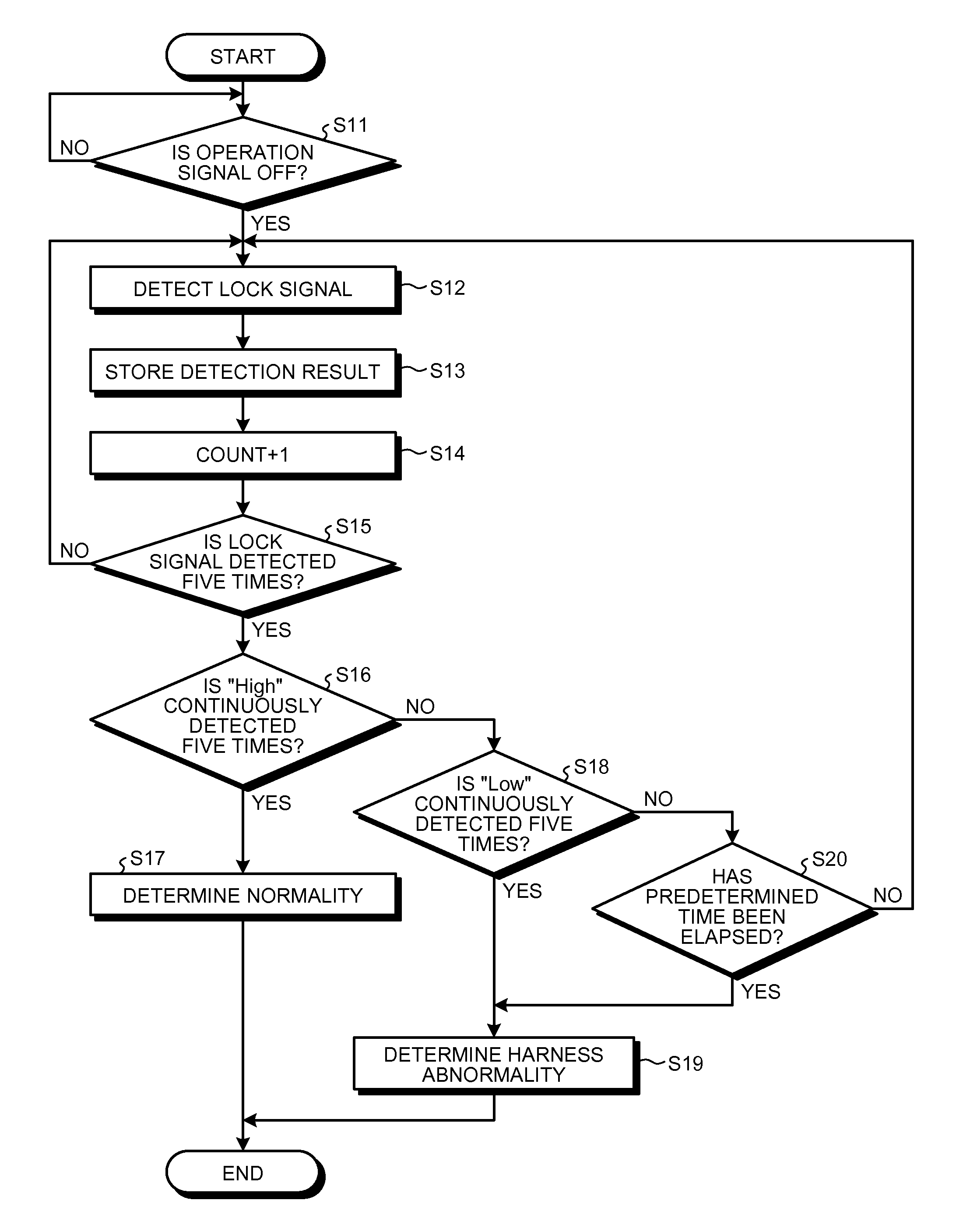
An abnormality monitoring system includes: an electronic component that outputs a lock signal of “High” when the electronic component stops functioning and outputs a lock signal of “Low” when the electronic component functions; a signal device that supplies power to the electronic component and outputs an ON operation signal instructing the electronic component to function and an OFF operation signal instructing the electronic component to stop functioning; a harness member that connects the electronic component and the signal device and transmits and receives a signal; and a monitor device that determines abnormality of the electronic component when the operation signal is ON and the lock signal is “Low”, and determines abnormality of the harness member when the operation signal is OFF and the lock signal is “Low”.

Description

CROSS-REFERENCE TO RELATED APPLICATIONS[0001]The present application claims priority to and incorporates by reference the entire contents of Japanese Patent Application No. 2013-162851 filed in Japan on Aug. 6, 2013.BACKGROUND OF THE INVENTION[0002]1. Field of the Invention[0003]The present invention relates to an abnormality monitoring system for an electronic component to and from which signals related to power supply and drive control is input and output through a harness member, and an image forming apparatus.[0004]2. Description of the Related Art[0005]In a recent electrophotographic image forming apparatus, its structure and control system have been complicated because of the speed-up of functions, high resolution, downsizing of the apparatus, or the like. In particular, the number of electronic components installed, such as various types of drive motors for driving internal drive units, is increased, and drive control with complicated timing and the like becomes necessary for...

Claims


Application Information

Patent Timeline
Patent Type & AuthorityPatents(United States)
IPC IPC(8): G03G15/00G01R31/00
CPCG03G15/55G03G15/5004G01R31/00
InventorKONISHI, TAKAHIROMORITA, YOSHIAKI
OwnerRICOH KK