Panoramic extended windshield with integrated non-moving blind

a technology of non-moving blinds and panoramic windows, applied in the direction of windows, windscreens, antiglare equipment, etc., can solve the problems of insufficient windscreens by themselves, unsuitable flat sliding panels, roll-up type sun shades, etc., to improve the vertical viewing area, move or eliminate the high turbulence/drag interface, good optics

Active Publication Date: 2016-06-14
MANNHEIM ASTETE MARIO ARTURO
View PDF23 Cites 10 Cited by
  • Summary
  • Abstract
  • Description
  • Claims
  • Application Information

AI Technical Summary

Benefits of technology

[0034]The trend towards low windshield installation angles with the roof sheet metal continuing tangent to the top of the windshield and making a large radii transition makes it possible to economically mass produce large windshields, having good optics in the transition area, which incorporate a substantial portion if not the entire roof section and even the rear window. Such a windshield moves or eliminates the high turbulence / drag interface between the glass and the sheet metal while providing the driver with an improved vertical viewing area and admitting more light into the passenger compartment.
[0036]To overcome consumer preference for a familiar aesthetic, rather than modulating the light transmittance of the entire sheet of switchable material, the material is segmented into electrically separate circuits or “slates” to form a structure emulating a window blind. The same can be done with the visors as well, emulating the familiar rectangular shape. A controlling means allows the blind to be opened or closed in any desired sequence. Said controlling means can be equipped with a programmable user interface, which can be a smart phone or tablet, allowing the user to modify and add sequences. Said controlling means also can operate a sound emitting means which can be programmed to produce any type of sound, as may be desired, synchronized with the operation of the blind. The sound of a plastic blind opening can be used to supplement the aesthetic of a conventional window blind. Or, the user may opt for: musical notes, a slamming dungeon door, a phasor gun or just about anything imaginable, the novelty of which will appeal to a large segment of the buying public.
[0038]The switchable material does not in any way encroach upon the vehicle headroom, is lighter than alternate implementations, has fewer parts, lower weight, lower labor, requires less vehicle assembly time and can be installed using the same tools, methods and systems already used to install windshields of the prior art.
[0039]In cold climates, high transmittance glass can be used, in conjunction with the blind, allowing the vehicle to take full advantage of the free solar energy while not overheating the vehicle on hot days.

Problems solved by technology

Such a windshield by itself is not adequate as a shading means must be provided.
Flat sliding panel and rollup type sun shades are not desirable as little space is available.

Method used


Image

  • Panoramic extended windshield with integrated non-moving blind
  • Panoramic extended windshield with integrated non-moving blind
  • Panoramic extended windshield with integrated non-moving blind

Examples


first embodiment

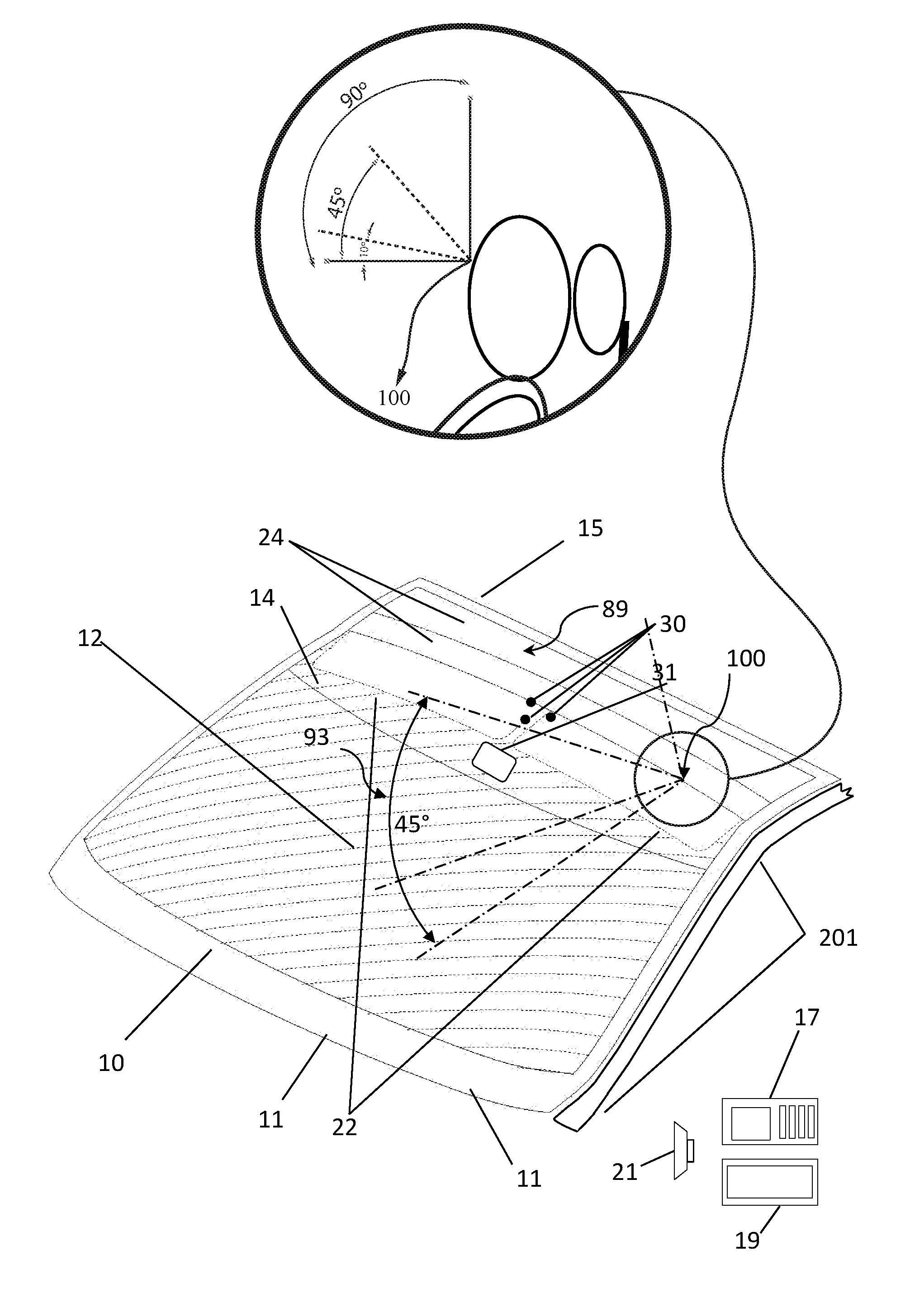
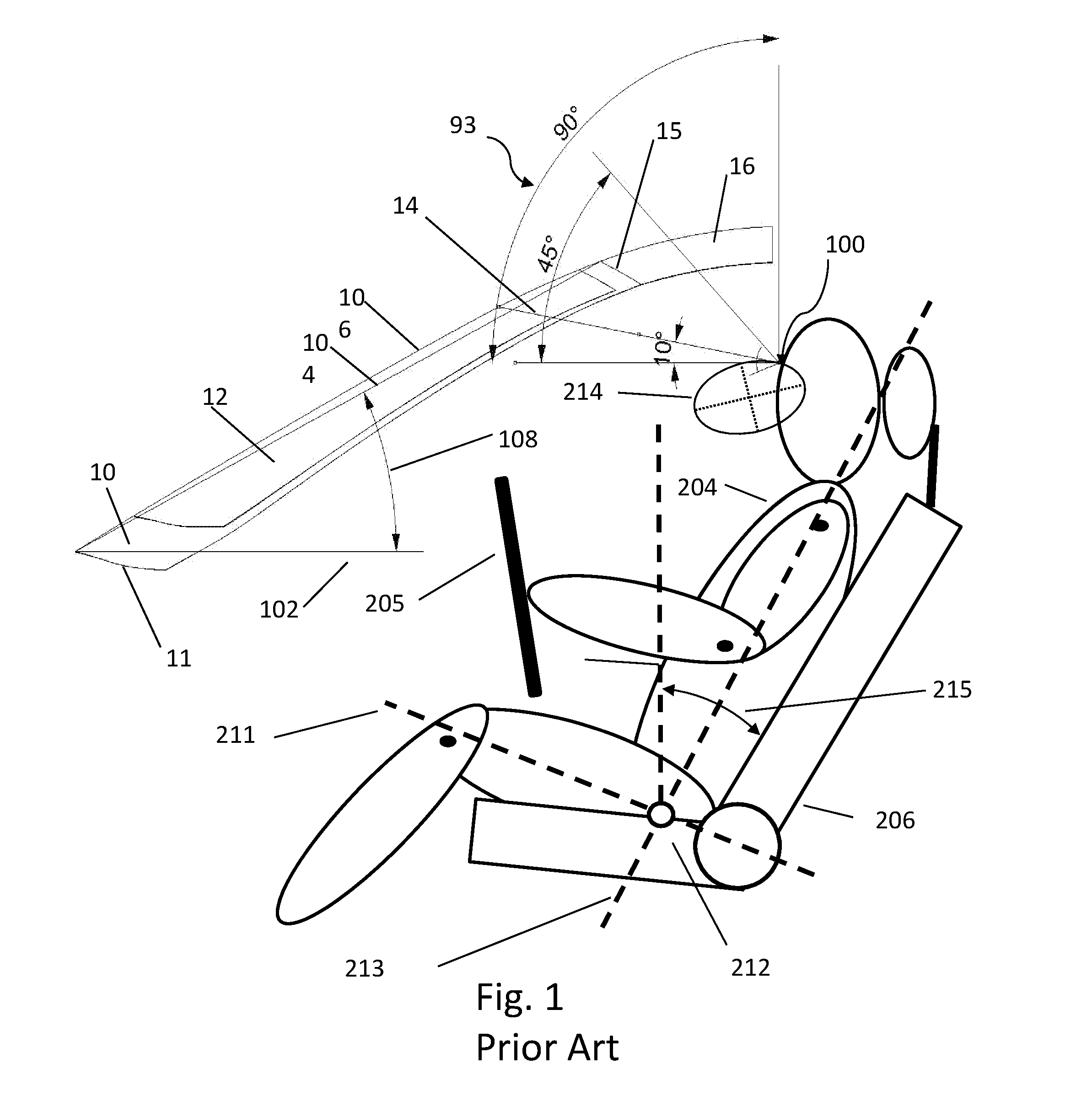
[0077]The present invention discloses a vehicle glazing comprising a windshield 12 having the top edge extended such as to provide the driver with an extended vertical viewing angle 93 of at least 45 degrees from the driver eye point as defined by SAE J903 and having an integrated electrically switchable blind system 89. The first embodiment is shown in FIG. 5 and is based upon the windshield 12 of FIG. 1. The bottom front edge 11 has a length of 1550 mm and the top edge 15 has a length of 1250 mm. The vertical centerline 106 length is ˜900 mm and the installation angle 108 is 23 degrees. FIG. 5 shows a mounting means in the form of three studs 30 for attachment to the glass of a center console, mirrors, cameras and other devices as may be required.

[0078]The radius of the transition between the top edge 15 of the windshield 12 and the portion of the roof 16 that is substantially horizontal is 2000 mm. This large radius provides the occupants a view having little if any noticeable op...

second embodiment

[0131]FIG. 6 shows a second embodiment of the present invention. The top edge 15 has been extended to include substantially the entire roof and includes a dual rectangular visor 22 and an 18 slat PDLC blind 28. The addition of the visor eliminates the need to mount a mechanical visor to the glass or A-pillar 201 (as shown on FIG. 19), adding to the advantages already presented in the first embodiment. All other details are the same as in Embodiment one.

third embodiment

[0132]FIG. 7 shows a third embodiment of the present invention. The top edge 15 has been extended to include substantially the entire roof and includes a segmented visor 32 extending to the AS1 line and an 18 slat PDLC blind 28. FIG. 8 shows the third embodiment with the slates in the area above the drive in the on state. All other details are the same as in Embodiment two.


PUM

PropertyMeasurementUnit
light transmittanceaaaaaaaaaa
angleaaaaaaaaaa

Abstract

A vehicle windshield with a top edge extended such as to provide a lower drag coefficient and giving the driver a wider panoramic vertical viewing angle and having an integrated shading means, having no movable parts and utilizing a material which is capable changing its light transmittance electrically and with a controlling means which mimics the aesthetics of a conventional mechanical blind. Aspects of the various embodiments include: switchable segmented sun visors, integrated solid state lighting, a mounting means for attachment of a center console, mirrors, cameras and other devices, a controlling means capable of providing a variety of opening and closing sequences, a user programmable interface, a touch screen interface, touch sensitive activation, a sound emitting means to provide for the audible aesthetic of the blind, inclusion of substantially the entire roof, inclusion of substantially the entire roof and the rear window, and any combination of a tinted, heat reflecting, heat absorbing or photo-chromic coating, film or interlayer in all or a portion of the glazing area.

Description

FIELD OF THE INVENTION[0001]The presently disclosed invention is directed to the use of electrically controlled variable light transmittance films, such as PDLC and SPD in a panoramic automotive glazing.BACKGROUND OF THE INVENTION[0002]Regulatory standards and specifications for products and processes are often written based upon an existing technology. This is understandable as it is a practical and pragmatic approach. Often, the ideal technology may not be economical or achievable. The primary problem over time with these technology based standards is that they are infrequently revised as the technology changes unless there is some compelling reason to do so.[0003]The forward driver vision requirements for vehicles are dictated by government regulations. The intent is to ensure that the driver has an adequate field of view to safely operate the vehicle. The ideal, based just upon human factors, would be to have an unobstructed view in all directions. This is not possible or practi...

Claims


Application Information

Patent Timeline
Patent Type & Authority Patents(United States)
IPC IPC(8): B60J1/00B32B17/00B60J3/04G02F1/01G02F1/167G02F1/1333B60R1/00
CPCB60J3/04B60R1/001G02F1/1333G02F1/167G02F1/0126B32B17/00B32B17/10504G02F1/1334G02F1/1675B32B2307/402B32B2307/422
Inventor MANNHEIM ASTETE, MARIO ARTUROSARMIENTO SANTOS, ANDRES FERNANDOCUERVO FIGUEREDO, CAMILO IGNACIOSERRANO REY, MANUEL LEONARDOSCHOTTBORGH RODRIGUEZ, JULIANAQUIJANO REYES, JIMMY ALEXANDERVOETZEL, CHARLES S.
Owner MANNHEIM ASTETE MARIO ARTURO
Why Eureka
Try Eureka