Voltage regulator and electronic apparatus

a voltage regulator and electronic equipment technology, applied in the direction of electric variable regulation, process and machine control, instruments, etc., can solve the problem of large overshooting of output voltage, and achieve the effect of preventing erroneous operations or malfunctions and suppressing the occurrence of overshooting

Active Publication Date: 2016-07-26
ABLIC INC
View PDF5 Cites 0 Cited by
  • Summary
  • Abstract
  • Description
  • Claims
  • Application Information

AI Technical Summary

Benefits of technology

[0013]The voltage regulator according to the invention can suppress the occurrence of overshooting in the output voltage at the starting time at which the circuitry is turned on from a state in which the circuitry is turned off by the ON / OFF circuit by supplying a source voltage.
[0014]It is also possible to prevent erroneous operations or malfunction of a portable apparatus or an electronic apparatus that operates using the voltage regulator as a power source.

Problems solved by technology

However, the voltage regulator according to the related art has a problem in that the current Ix2 is not supplied to the gate of the output transistor at a proper time and thus great overshooting occurs in the output voltage when the source voltage rapidly increases such as when starting the power source.

Method used


Image

  • Voltage regulator and electronic apparatus
  • Voltage regulator and electronic apparatus
  • Voltage regulator and electronic apparatus

Examples


Embodiment Construction

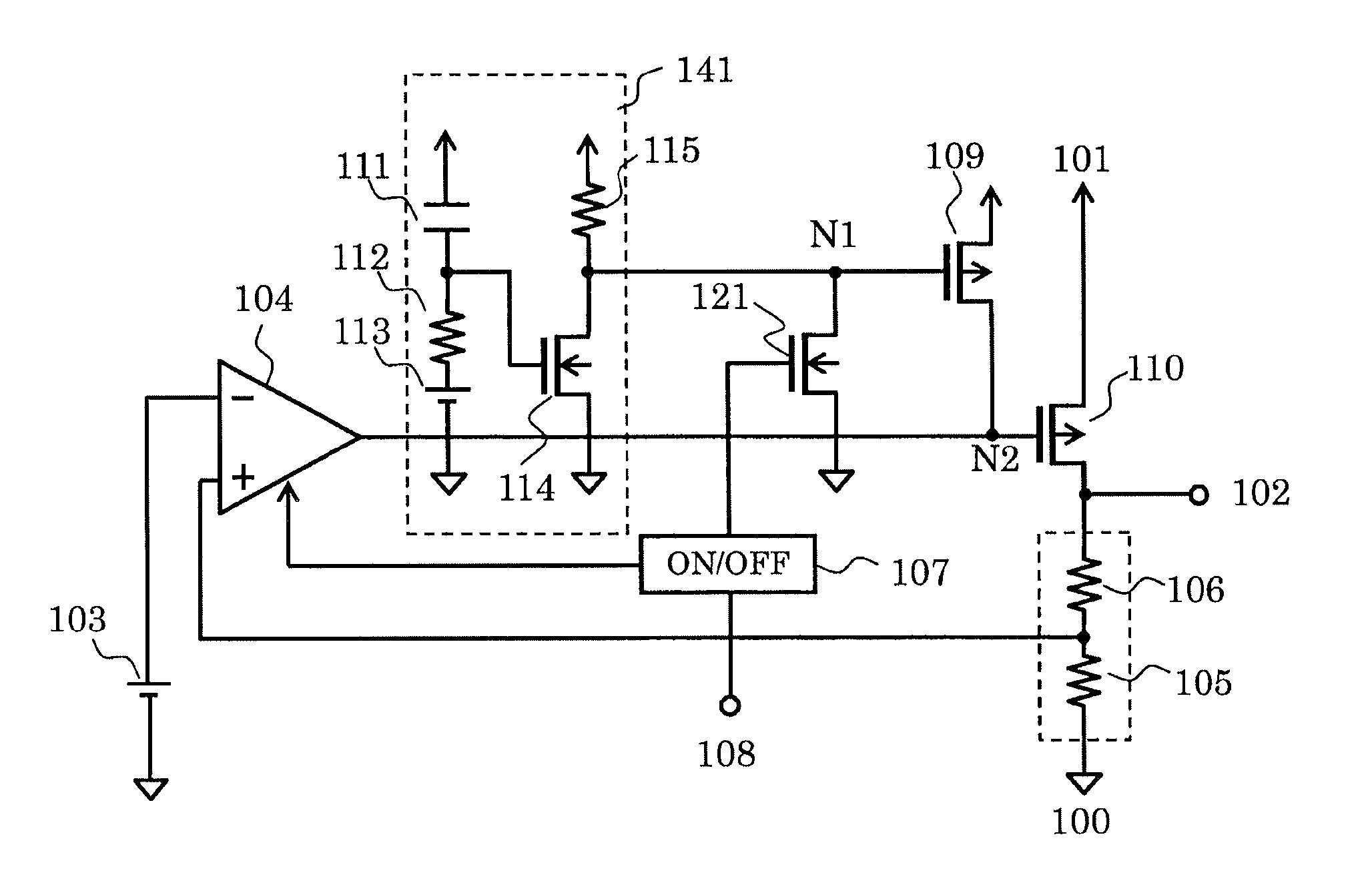
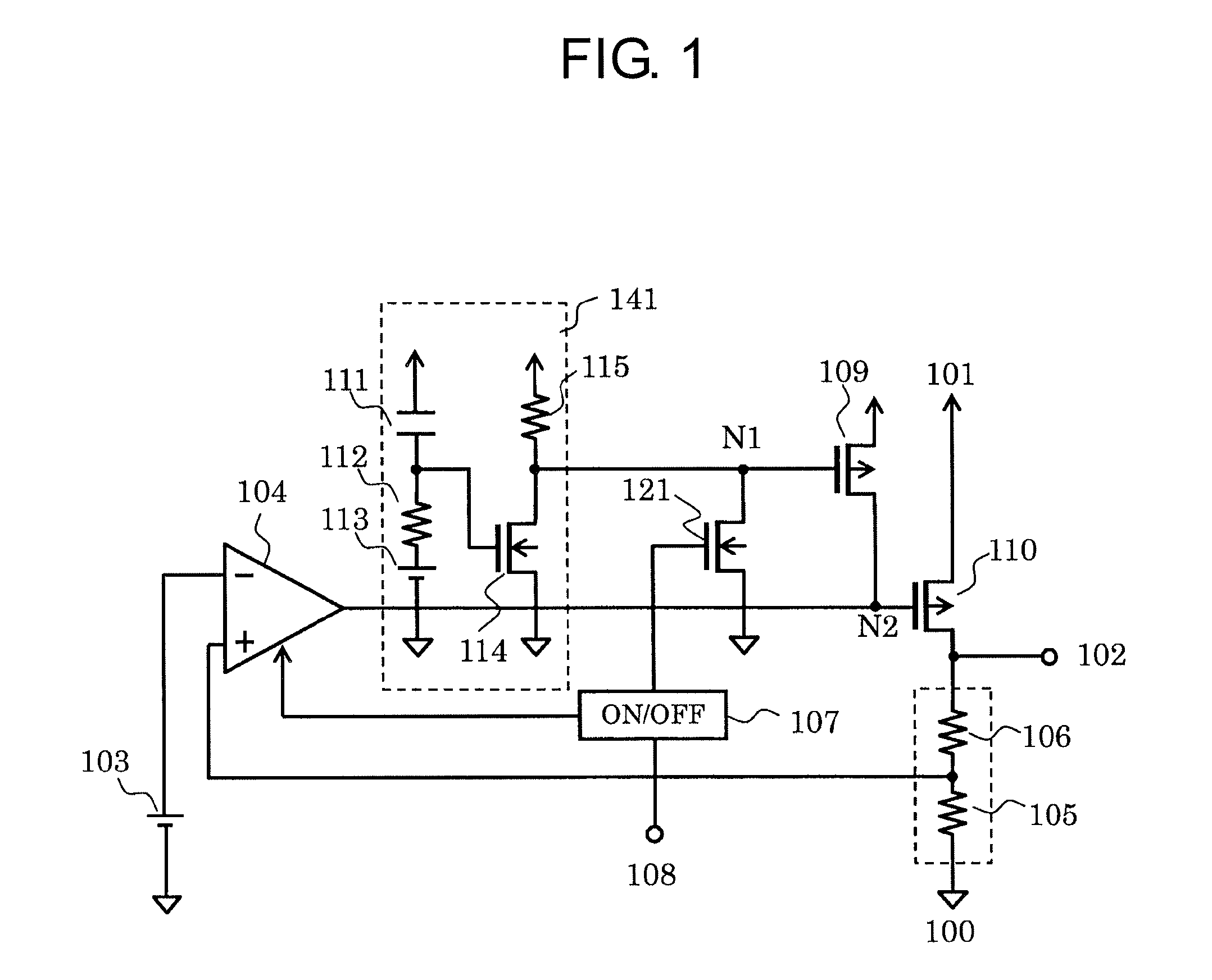
[0018]FIG. 1 is a circuit diagram illustrating an example of a voltage regulator according to an embodiment of the invention.

[0019]The voltage regulator according to this embodiment includes an error amplifier circuit 104, a reference voltage circuit 103, resistors 105 and 106 constituting a voltage divider circuit, PMOS transistors 109 and 110, NMOS transistors 114 and 121, resistors 112 and 115, a capacitor 111, a constant voltage circuit 113, an ON / OFF circuit 107, a ground terminal 100, a power source terminal 101, an output terminal 102, and an ON / OFF control terminal 108.

[0020]The capacitor 111, the resistors 112 and 115, the constant voltage circuit 113, and the NMOS transistor 114 constitute a source voltage fluctuation detector circuit 141. The PMOS transistor 109 constitutes an overshooting control circuit. The ON / OFF circuit 107 controls ON and OFF states of circuits of the voltage regulator using ON / OFF signals input to the ON / OFF control terminal 108 from the outside. H...


PUM


Abstract

A voltage regulator is provided which can suppress an occurrence of overshooting in an output voltage at the time of starting a power source with a source voltage or the like. The voltage regulator includes an error amplifier circuit, an overshooting control circuit that is connected to the gate of an output transistor, and an ON/OFF circuit that controls ON and OFF states of at least the error amplifier circuit. Here, the ON/OFF circuit controls the overshooting control circuit so as to turn on the output transistor when a predetermined time passes after at least the error amplifier circuit is turned on at the time of starting the voltage regulator.

Description

RELATED APPLICATIONS[0001]This application claims priority under 35 U.S.C. §119 to Japanese Patent Application No. 2013-273240 filed on Dec. 27, 2013, the entire content of which is hereby incorporated by reference.BACKGROUND OF THE INVENTION[0002]1. Field of the Invention[0003]The present invention relates to a voltage regulator that is disposed as a power source of a portable apparatus or an electronic apparatus so as to output a constant voltage, and more particularly, to a voltage regulator that can suppress an occurrence of overshooting in an output voltage at the time of starting a power source with a source voltage.[0004]2. Background Art[0005]A voltage regulator according to the related art will be described below. FIG. 3 is a circuit diagram illustrating a voltage regulator according to the related art.[0006]The voltage regulator according to the related art includes an error amplifier circuit 104, a reference voltage circuit 103, PMOS transistors 901 and 902, an output tra...

Claims


Application Information

Patent Timeline
Patent Type & Authority Patents(United States)
IPC IPC(8): G05F1/571G05F1/575G05F1/56G05F1/46G05F1/565
CPCG05F1/571G05F1/575G05F1/468G05F1/562G05F1/565
Inventor TOMIOKA, TSUTOMUSUGIURA, MASAKAZU
Owner ABLIC INC
Why Eureka
Try Eureka