Spring ring circuit assembly

a technology of spring ring and circuit assembly, which is applied in the direction of current collectors, electrical devices, rotary current collectors, etc., can solve the problems of affecting the transmission of power and electrical signals between stationary objects, affecting the service life of spring ring, so as to prevent longitudinal movement of rollers and prevent electrical shorting

Active Publication Date: 2016-10-18
NOVAWURKS
View PDF14 Cites 2 Cited by
  • Summary
  • Abstract
  • Description
  • Claims
  • Application Information

AI Technical Summary

Benefits of technology

[0017]Preferably, the spring ring, inner and outer sets of rollers, and circular band are structurally confined to stay substantially within a plane. In a first preferred embodiment, the inner rollers may be constructed to have convex outer circumferential surfaces to mate within concave outer circumferential surfaces of the outer rollers (or vice versa) so as to longitudinally lock the rollers within a plane. However, in a preferred embodiment, the spring ring, circular band, inner set of rollers and outer set of rollers are cylindrical and sandwiched between two insulator plates made of non-electrically conductive material. The two layers of non-electrically conductive m...

Problems solved by technology

There has long been difficulty in transmitting power and electrical signals between a stationary object and a rotating structure.
Unfortunately slip rings suffer from several disadvantages.
The wiping action can create wear on both the finger and contact surface.
Excessive wear results in the need to readjust the finger or its contact surface to compensate for the wear and ensure a proper electrical contact.
Similarly, the excessive wear can cause debris which contaminates the ar...

Method used


Image

  • Spring ring circuit assembly
  • Spring ring circuit assembly
  • Spring ring circuit assembly

Examples


Embodiment Construction

[0023]While the present invention is susceptible of embodiment in various forms, as shown in the drawings, hereinafter will be described the presently preferred embodiments of the invention with the understanding that the present disclosure is to be considered as an exemplification of the invention, and it is not intended to limit the invention to the specific embodiments illustrated.

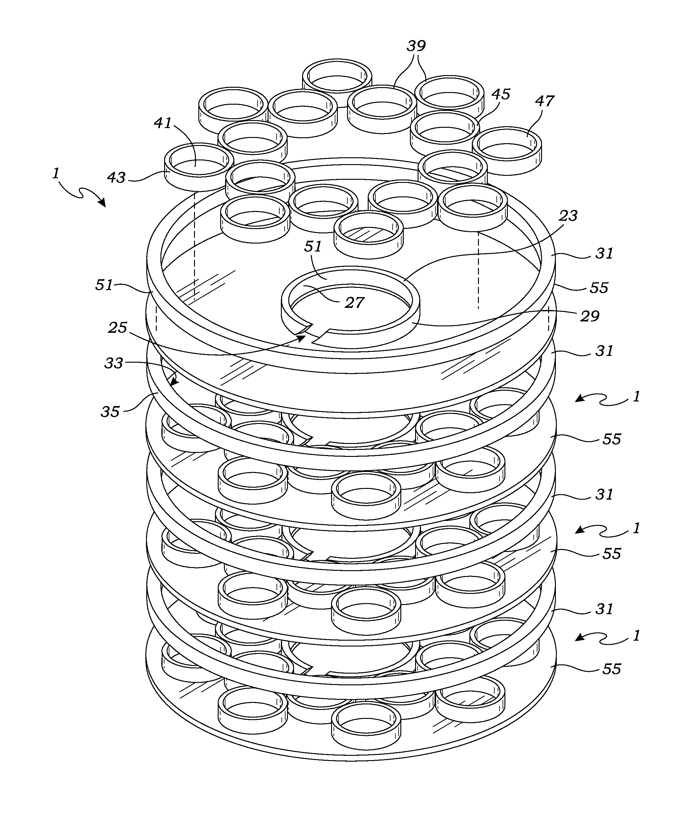
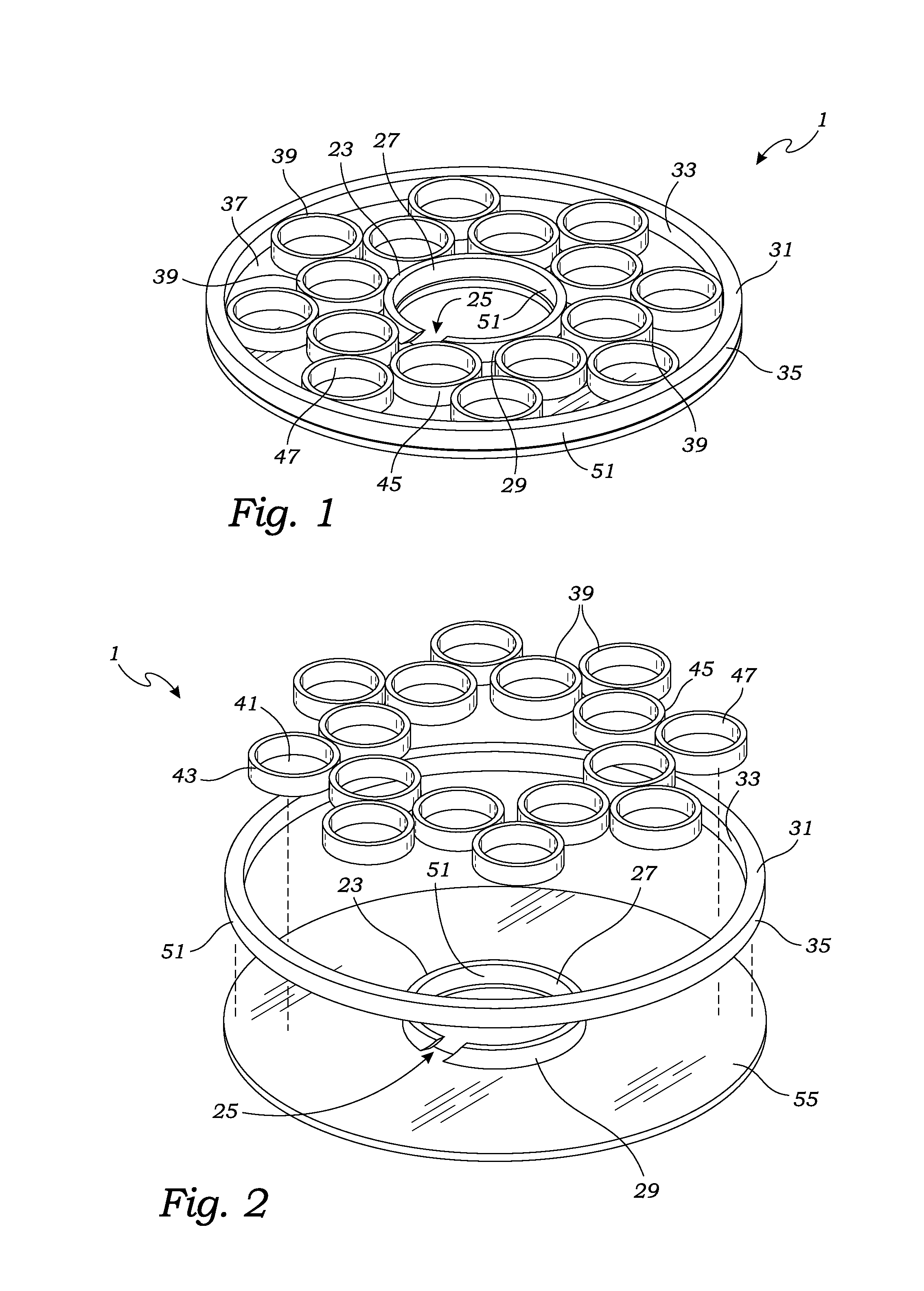
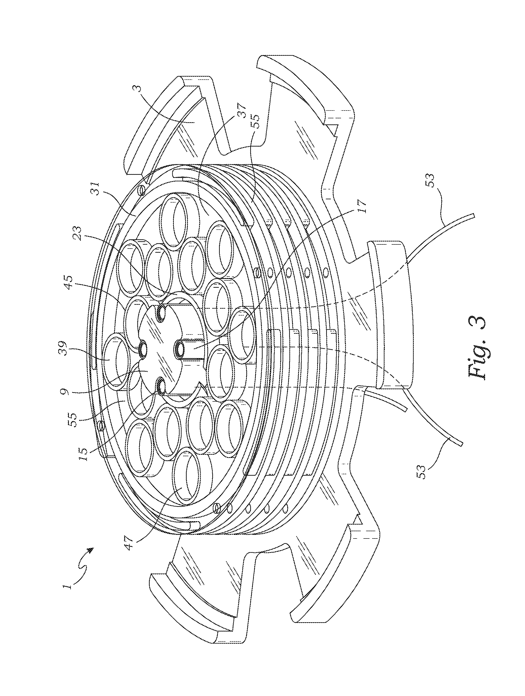
[0024]With reference to FIGS. 1-4, the spring ring circuit assembly 1 provides for one or more electrical circuits for transmitting power or electrical signals between a stationary first structure and a rotating second structure. A preferred spring ring circuit assembly 1 for providing a single electrical pathway is illustrated in FIGS. 1 and 2. As illustrated in these figures, the spring ring 1 circuit assembly includes a spring ring 23 having a substantially circular structure. The spring ring is affixed to a first structure 3 by concentrically mounting the spring ring to a pillar-like structure refer...


PUM


Abstract

A spring ring circuit assembly is provided for transmitting electricity between a first structure and a second structure which rotates relative to the first structure. The spring ring circuit assembly includes a spring ring which is affixed to and concentrically positioned around a spindle. The spring ring circuit assembly further includes a circular band concentrically positioned around the spring ring so as to create an annular space between the spring ring and circular band. The spring ring circuit assembly further includes an inner set of rollers positioned around and engaging the spring ring, and an outer set of rollers positioned within and engaging the circular band. The spring ring, rollers and circular band are made of electrically conductive materials so as to allow electricity to transmit between the spring ring and the circular band which is capable of rotating around the spring ring.

Description

[0001]This invention was made with government support under contract no. HR0011-14-C-0023 awarded by the Defense Advanced Research Projects Agency. The government has certain rights in the invention.BACKGROUND OF THE INVENTION[0002]The present invention relates generally to mechanisms providing for the transmission of power and electrical signals between a stationary structure and a rotating structure.[0003]There has long been difficulty in transmitting power and electrical signals between a stationary object and a rotating structure. A well-known structure for accomplishing this is a “slip ring”. Typically, a slip ring includes a metal contact, referred to as a brush, which rubs on the circumferential or radial surface of a rotating metal ring. As the metal ring rotates, an electrical current is conducted through the stationary brush. If more than one electric circuit is required, additional ring and brush assemblies are coaxially positioned and stacked to rub against the radial su...

Claims


Application Information

Patent Timeline
IPC IPC(8): H01R39/64
CPCH01R39/643H01R2201/26
Inventor JAEGER, TALBOT
Owner NOVAWURKS
Why Eureka
Try Eureka