Sealed connector with an extended seal sleeve and an anti-water pooling retainer

a technology of sealing seal and retainer, which is applied in the direction of coupling base/case, coupling device connection, electrical apparatus, etc., can solve the problems of cable seals used in electrical connectors for large cross section cables that can lose sealing compression, and fail to meet the volume of spa

Active Publication Date: 2017-02-21
APTIV TECH LTD
View PDF5 Cites 8 Cited by
  • Summary
  • Abstract
  • Description
  • Claims
  • Application Information

AI Technical Summary

Benefits of technology

[0009]The retainer may substantially fill the volume of the space within the terminal cavity from the cable seal to the distal end of the terminal cavity. The retainer may provide cable motion strain relief and maintain compression between the cable seal and the cavity inner wall.

Problems solved by technology

Cable-to-cable and cable-to-device sealed electrical connectors are subject to performance issues caused by vibration, motion, and routing of large, heavy, stiff cables (e.g. cables with a cross section greater than 6 mm2).
Cable seals used in electrical connectors for large cross section cables can lose sealing compression when cables are moved or routed away extreme angles.
These loose fitting retainers allow cable vibration to be readily transmitted into the electrical connector terminal causing electrical contact fretting corrosion and / or wear, leading to failure of that electrical connection.
This water can then leak past the seal and cause corrosion of the terminal or cause damage to the connector if the water freezes.
Typically, a loose plastic retainer is used to limit cable motion to maintain sealing performance, but vibration performance is poor, and water can pool in the connector terminal cavity causing cable seal failure.
Other previous solutions have included cable seals with insert molded plastic stiffeners, these seals are very expensive, while providing strain relief and vibration dampening of the cable, they do not completely block water pooling in the terminal cavity.

Method used


Image

  • Sealed connector with an extended seal sleeve and an anti-water pooling retainer
  • Sealed connector with an extended seal sleeve and an anti-water pooling retainer
  • Sealed connector with an extended seal sleeve and an anti-water pooling retainer

Examples


Embodiment Construction

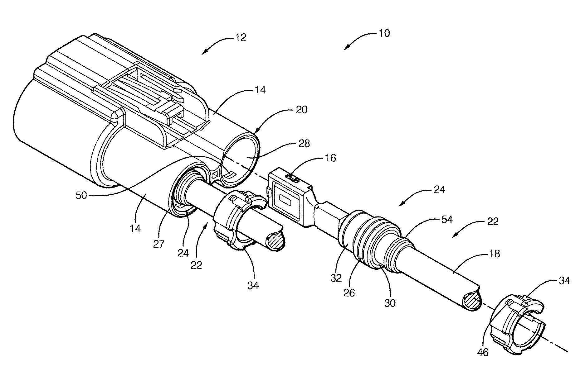
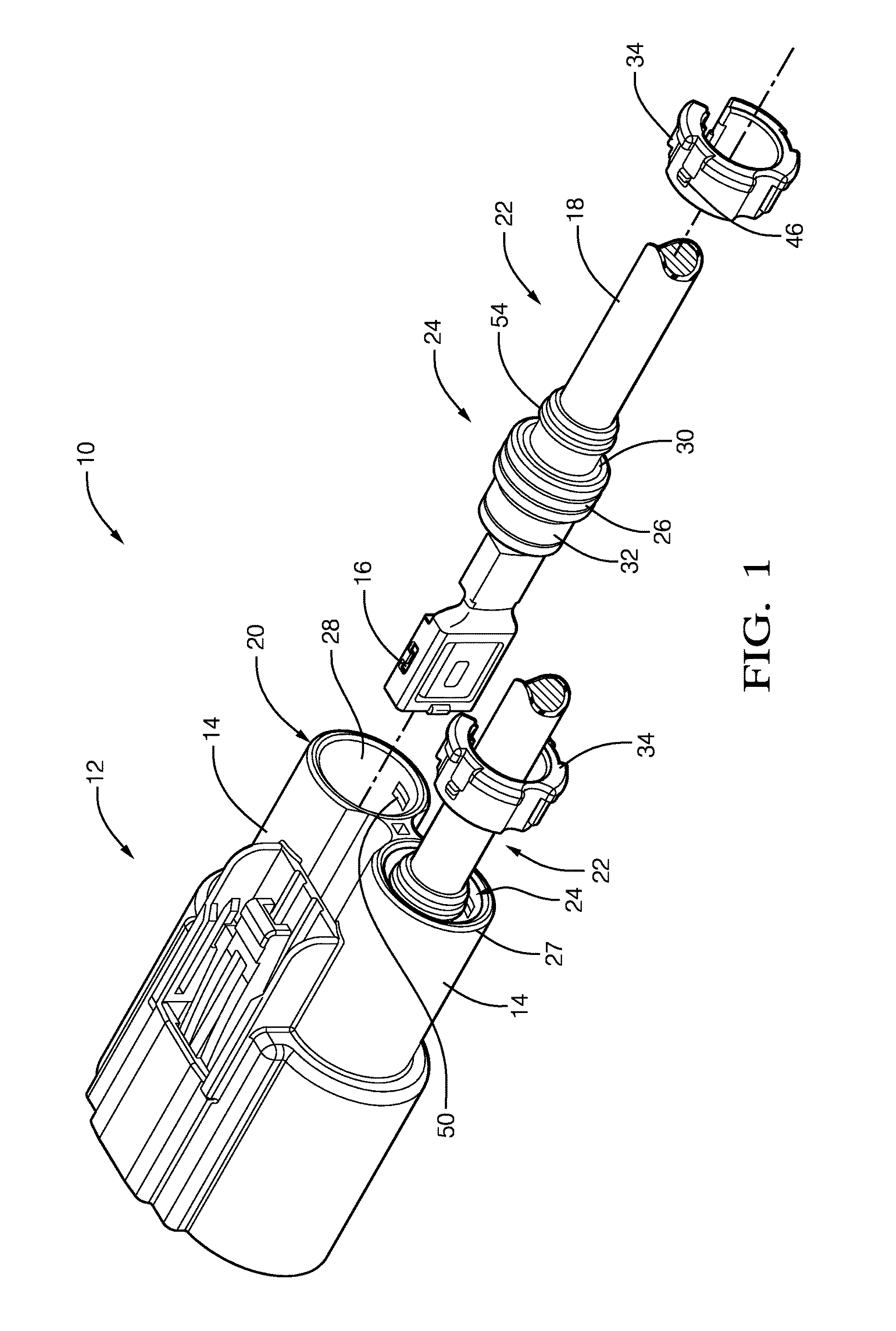
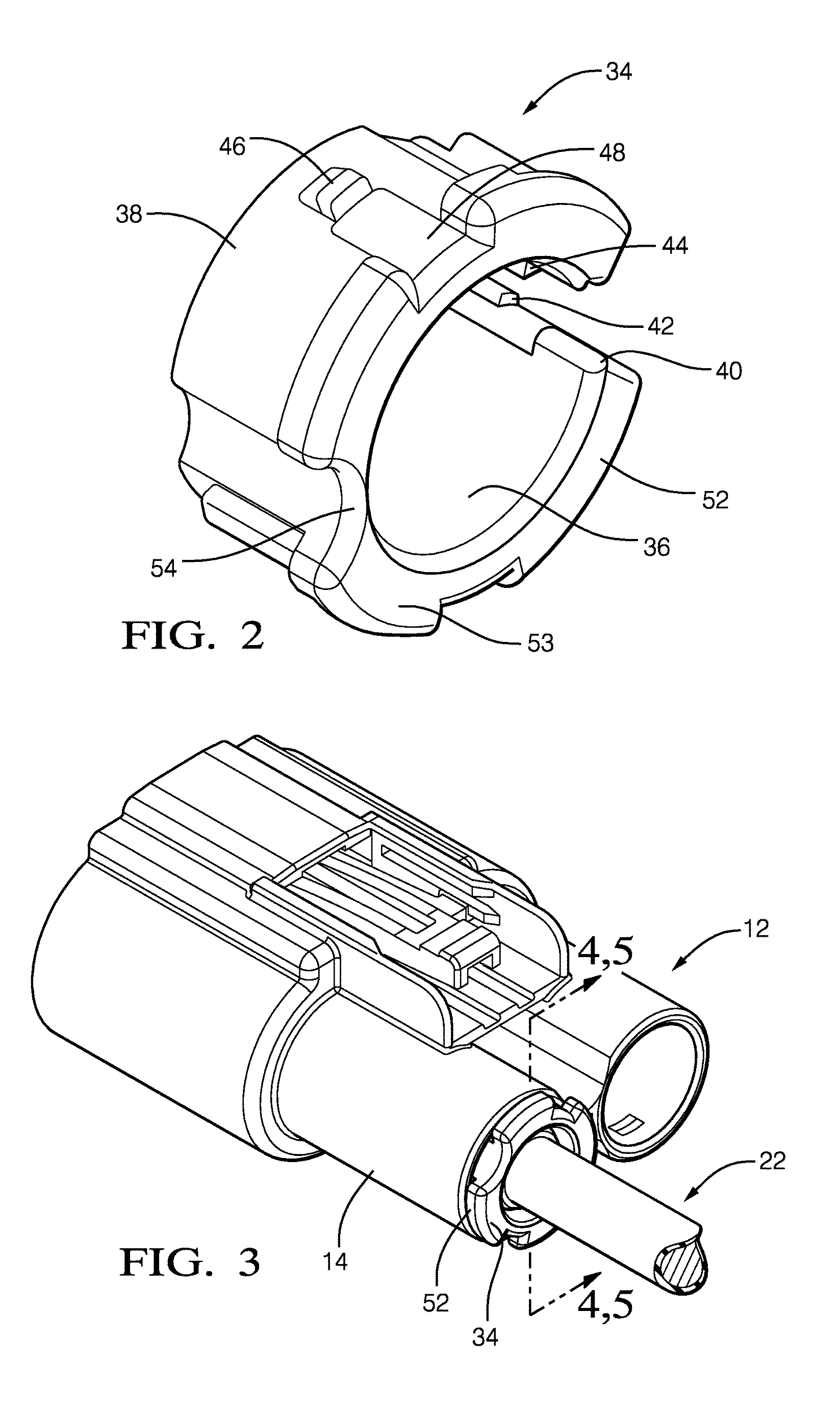
[0017]A connector that includes a connector body, terminated cables, individual cable seals surrounding each terminated cable, and seal retainers configured to secure the cable seals within the connector body is presented herein. Each cable seal includes a sleeve that covers the cable from the sealing ring of the cable seal to a point on the cable near the end of the terminal cavity. The seal retainer is fitted over the sleeve, substantially filling the volume between the sleeve and the inner wall of the terminal cavity, providing cable motion strain relief, maintaining compression between the cable seal and the cavity inner wall, and preventing water from collecting within the terminal cavity. As used herein, substantially filling means that the seal retainer occupies at least ninety percent of the volume between the sleeve and the inner wall of the terminal cavity.

[0018]FIG. 1 illustrates a non-limiting example of a connector 10. The connector 10 includes a connector body 12 havin...


PUM


Abstract

An connector includes a terminated cable, a connector body defining a cylindrical terminal cavity configured to receive the terminated cable, and a cable seal axially surrounding a portion of the terminated cable. The cable seal defines a compliant primary sealing ring that is in compressive contact with an inner wall of the terminal cavity. The cable seal further defines an extended sleeve. The connector also includes a seal retainer that is inserted within a distal end of the terminal cavity and axially surrounds at least a portion of the extended sleeve. An inner surface of the seal retainer is proximate at least a portion of the extended sleeve and an outer surface of the seal retainer is proximate the inner wall of the terminal cavity.

Description

CROSS-REFERENCE TO RELATED APPLICATION[0001]This application claims the benefit under 35 U.S.C. §119(e) of U.S. Provisional Patent Application No. 61 / 977,329 filed Apr. 9, 2014, the entire disclosure of which is hereby incorporated herein by reference.TECHNICAL FIELD OF THE INVENTION[0002]The invention generally relates to a sealed connector, and more particularly relates to a connector having a seal with an extended sleeve and a seal retainer configured to dampen vibration of a cable and inhibit retention of water within the connector.BACKGROUND OF THE INVENTION[0003]Cable-to-cable and cable-to-device sealed electrical connectors are subject to performance issues caused by vibration, motion, and routing of large, heavy, stiff cables (e.g. cables with a cross section greater than 6 mm2). Cable seals used in electrical connectors for large cross section cables can lose sealing compression when cables are moved or routed away extreme angles. Prior art connectors have incorporated plas...

Claims


Application Information

Patent Timeline
Patent Type & Authority Patents(United States)
IPC IPC(8): H01R13/52
CPCH01R13/5205H01R13/5208H01R13/5221
Inventor CAMPBELL, JEFFREY SCOTTWEBER, JR., WESLEY W.
Owner APTIV TECH LTD
Why Eureka
Try Eureka