Pivoting arrangement

a technology of rotating arrangement and spring, which is applied in the direction of metal working apparatus, etc., can solve the problem of limited active range of spring loading arrangement, and achieve the effect of less variation of resting position

Active Publication Date: 2017-06-13
KONINK PHILIPS ELECTRONICS NV
View PDF44 Cites 15 Cited by
  • Summary
  • Abstract
  • Description
  • Claims
  • Application Information

AI Technical Summary

Benefits of technology

[0006]It is an object of the present invention to overcome this problem, and to provide a pivoting arrangement for a device having a contour following function such as e.g. a shaving device with less variation of the resting position.
[0007]This and other objects are achieved by a pivoting arrangement for a device having a contour following function such as e.g. a shaving device, comprising a pivoting member, adapted to support a shaving head, a cradle, pivotally supporting the pivoting member, and a spring loading arrangement comprising at least one deformable spring element, and arranged to interact with the pivoting member in a first point of action to exert a force acting to move the pivoting member in a first pivoting direction, and in a second point of action to exert a force acting to move the pivoting member in a second pivoting direction, the spring loading arrangement thereby biasing the pivoting member in a resting position. The spring loading arrangement further has a limited active range, so that, when the pivoting member is brought out of the resting position in the first pivoting direction, the spring loading arrangement is prevented from interacting with the pivoting member in the first point of action, and when the pivoting member is brought out of the resting position in the second pivoting direction, the spring loading arrangement is prevented from interacting with the pivoting member in the second point of action.
[0008]The active range of the spring loading arrangement is thus limited, so that the spring loading arrangement will only exert forces that act to return the pivoting member to its resting position. As a result, the resting position will not be dependent on e.g. the spring constants of different springs in the spring loading arrangement. The resting position will thus be more exactly defined, and exhibit less variation than conventional solutions. Also, the total force acting on the pivoting member will be reduced, thus causing less friction, also serving to improve the predictability of the arrangement.

Problems solved by technology

The active range of the spring loading arrangement is thus limited, so that the spring loading arrangement will only exert forces that act to return the pivoting member to its resting position.
Such a “free” angular range may be caused by play in the mechanical construction, or be a result of wear.

Method used


Image

  • Pivoting arrangement
  • Pivoting arrangement
  • Pivoting arrangement

Examples


Embodiment Construction

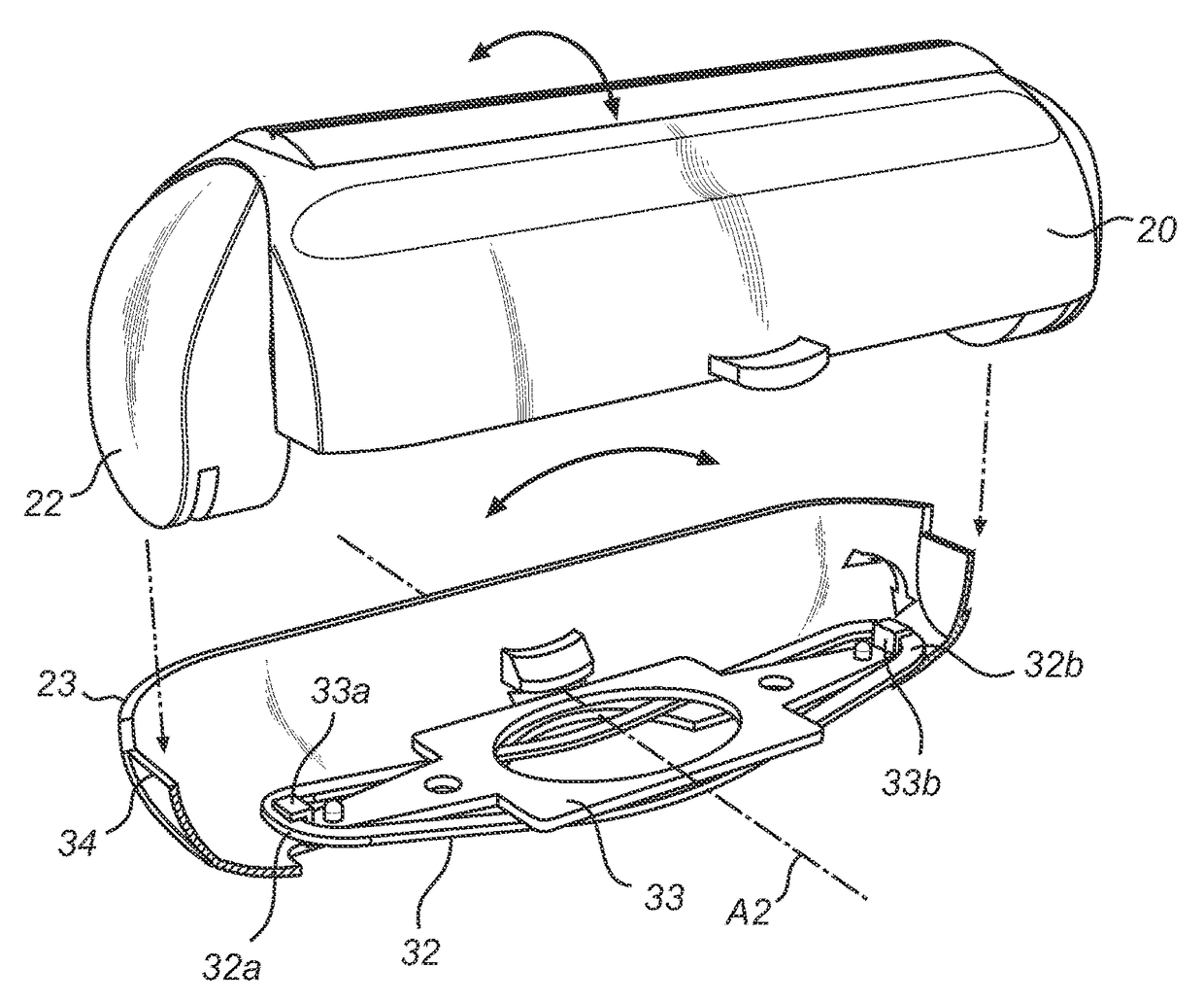
[0037]The following embodiments of pivoting arrangements according to the present invention may be useful in various types device having a contour following function such as e.g. shaving or grooming devices, where a contour following head such as e.g. a shaving head may be supported by the pivoting member, so as to allow for a contour following function. The following embodiments show the invention being implemented in a device having a shaving function. However, it should be noted that the invention is not limited to shaving devices as such and that the embodiments show non-limiting examples of the invention. Therefore, the details of the shaving device itself and its function will be described only very briefly, as they are not immediately relevant for the description of the present invention.

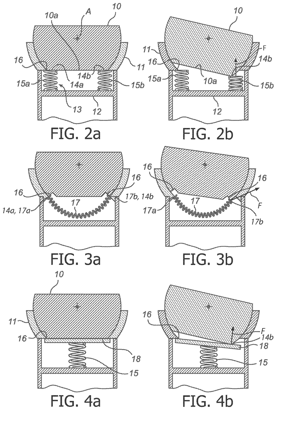
[0038]The pivoting arrangement shown in FIG. 2a comprises a pivoting member 10, which is pivotally arranged in a cradle 11. The cradle 11 is in turn arranged on a supporting structure, here r...


PUM


Abstract

A pivoting arrangement for a shaving device, comprising a pivoting member (10), adapted to support a shaving head, a cradle (11), pivotally supporting the pivoting member, and a spring loading arrangement (13) arranged to bias the pivoting member in a resting position. The spring loading arrangement has a limited active range, so that, when the pivoting member is brought out of the resting position in a first pivoting direction, the spring loading arrangement is prevented from interacting with the pivoting member in a first point of action (14a), and when the pivoting member is brought out of the resting position in a second pivoting direction, the spring loading arrangement is prevented from interacting with the pivoting member in a second point of action (14b). As a result, the resting position will not be dependent on e.g. the spring constants of different springs in the spring loading arrangement. The resting position will thus be more exactly defined, and exhibit less variation than conventional solutions. Also, the total force acting on the pivoting member will be reduced, thus causing less friction, also serving to improve the predictability of the arrangement.

Description

FIELD OF THE INVENTION[0001]The present invention relates to a pivoting arrangement for a device having a contour following function such as e.g. a shaving device.BACKGROUND OF THE INVENTION[0002]Conventional shaving and grooming devices are sometimes equipped with a pivoting arrangement providing a contour following function. Contour following functions are known from other devices as well such as epilators, skin rejuvenation, wrinkle treatment and trimming devices. In some pivoting arrangements, a moving part of the shaving head is spring loaded towards an extreme angular position, so that it assumes this extreme position when it is not submitted to any external forces.[0003]In other pivoting arrangements a moving part of the shaving head is arranged to assume a predefined resting position, e.g. a middle position, when it is not submitted to any external forces. This resting position can be spring loaded.[0004]Such a conventional middle position pivoting arrangement is known from ...

Claims


Application Information

Patent Timeline
Patent Type & Authority Patents(United States)
IPC IPC(8): B26B19/48B26B19/04
CPCB26B19/048B26B19/04B26B19/044B26B19/3806
Inventor BEUGELS, JOHANNESKNOPH, RAY
Owner KONINK PHILIPS ELECTRONICS NV
Why Eureka
Try Eureka