Dumbbell structure

a technology of dumbbells and weights, applied in the field of dumbbell structures, can solve the problems of inconvenience for people when using dumbbells, and achieve the effect of restricting the movement range of the press operation column and quick changing of weights

Inactive Publication Date: 2010-08-17
CHEN HUNG LUNG
View PDF7 Cites 15 Cited by
  • Summary
  • Abstract
  • Description
  • Claims
  • Application Information

AI Technical Summary

Benefits of technology

[0010]A primary objective of the present invention is to provide a dumbbell comprising a hand grip, weights and press operation pieces, wherein each of the weights is configured with a hole provided with a clamping groove. Moreover, a clamping portion is located on two ends of the hand grip, and perpendicularly displaced clamping holes and fixing holes are defined on each of the clamping portions. An end surface of each of the clamping portions is configured with a press operation recess, and a clamping column is located within each of the clamping holes. A spring is mounted on an end of each of the clamping columns, and a clamping end is located at the other end. Moreover, the center section of each of the clamping columns is configured with an actuating groove. A press operation column is disposed within each of the press operation recesses; a spring is mounted on an end of each of the press operation column, and a press operation end is located on the other end. Center sections of the press operation columns are respectively configured with a locating hole, and a fixing pin is disposed within each of the fixing holes and penetrates the respective locating holes of the press operation columns, thereby preventing the press operation column from dropping out of the press operation recess and restricting movement range of the press operation column. When force is applied to the press operation column using the press operation piece, then the press operation end of the press operation column exerts force on the actuating groove of the clamping column, thereby causing the clamping end of the clamping column to separate from the clamping groove within the weight. When the general user wants to change the weights, merely respectively using the press operation piece to press down on the press operation column enables the weight to be taken off; and when putting on the weights, merely respectively joining the clamping portion into the hole of the weight enables the clamping end of the clamping column to enter the clamping groove, thereby enabling weights of different weight to be put onto the hand grip, and achieving the objective of quick changing of the weights.

Problems solved by technology

However, because of the usually bulky size and expensive cost of fitness equipment, thus, the general public normally goes to a health club to keep fit.
However, although use of the dumbbell is widespread, nonetheless, because the objective of physical exercise of each exerciser and physical ability is different, thus, different exercisers frequently require different weights and often need to choose and match different weights.
Accordingly, complicated and time-consuming changing of the weights results in inconvenience for people when using the dumbbells.

Method used


Image

  • Dumbbell structure
  • Dumbbell structure
  • Dumbbell structure

Examples


Embodiment Construction

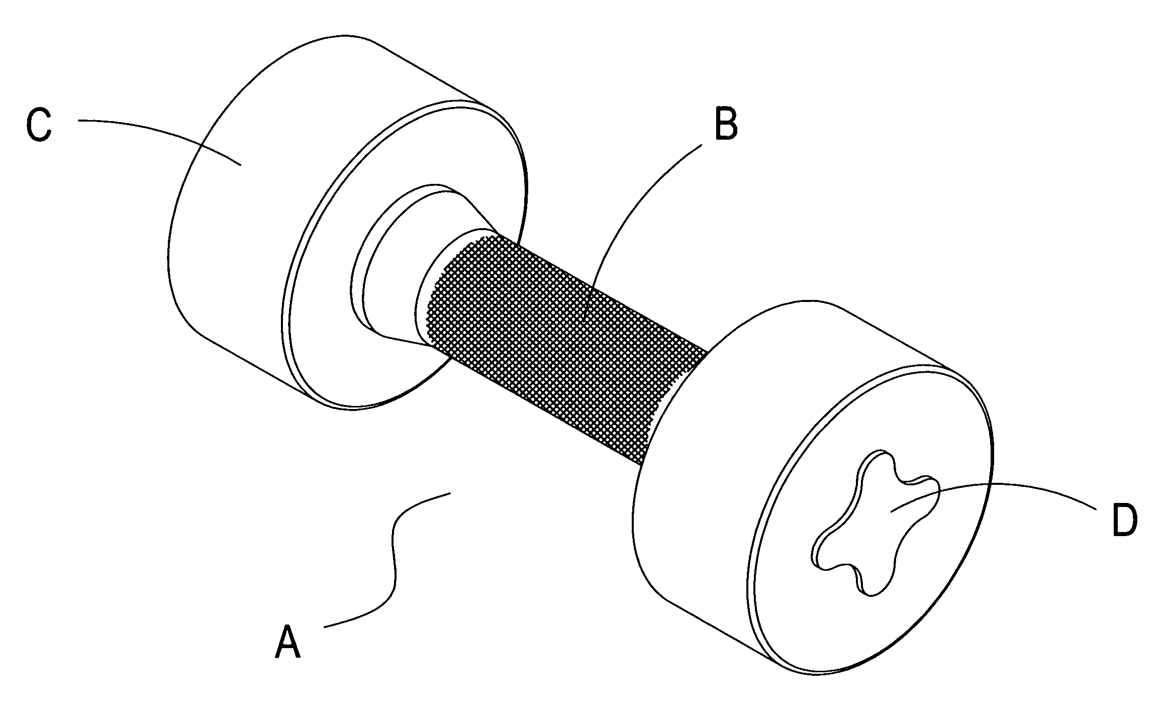
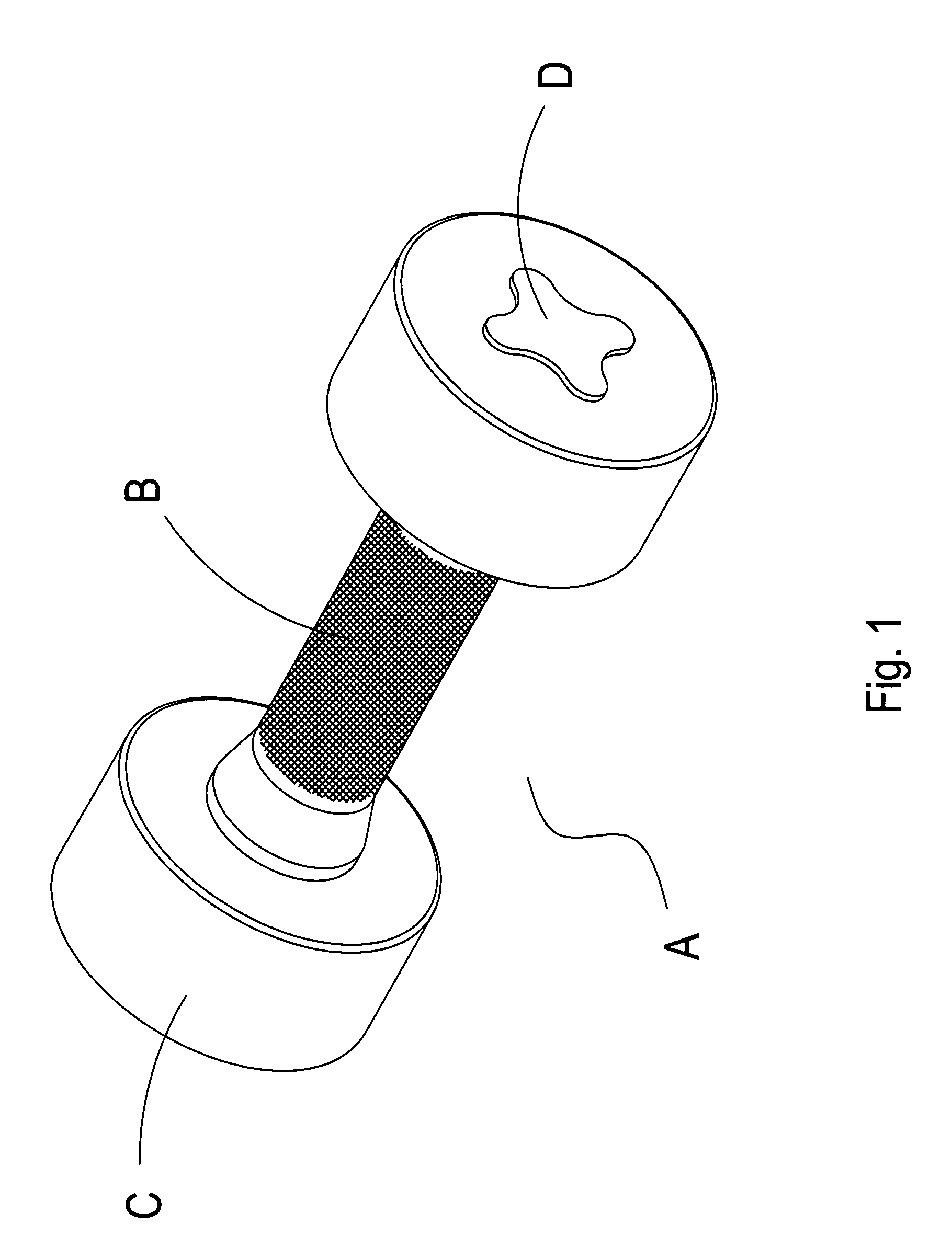
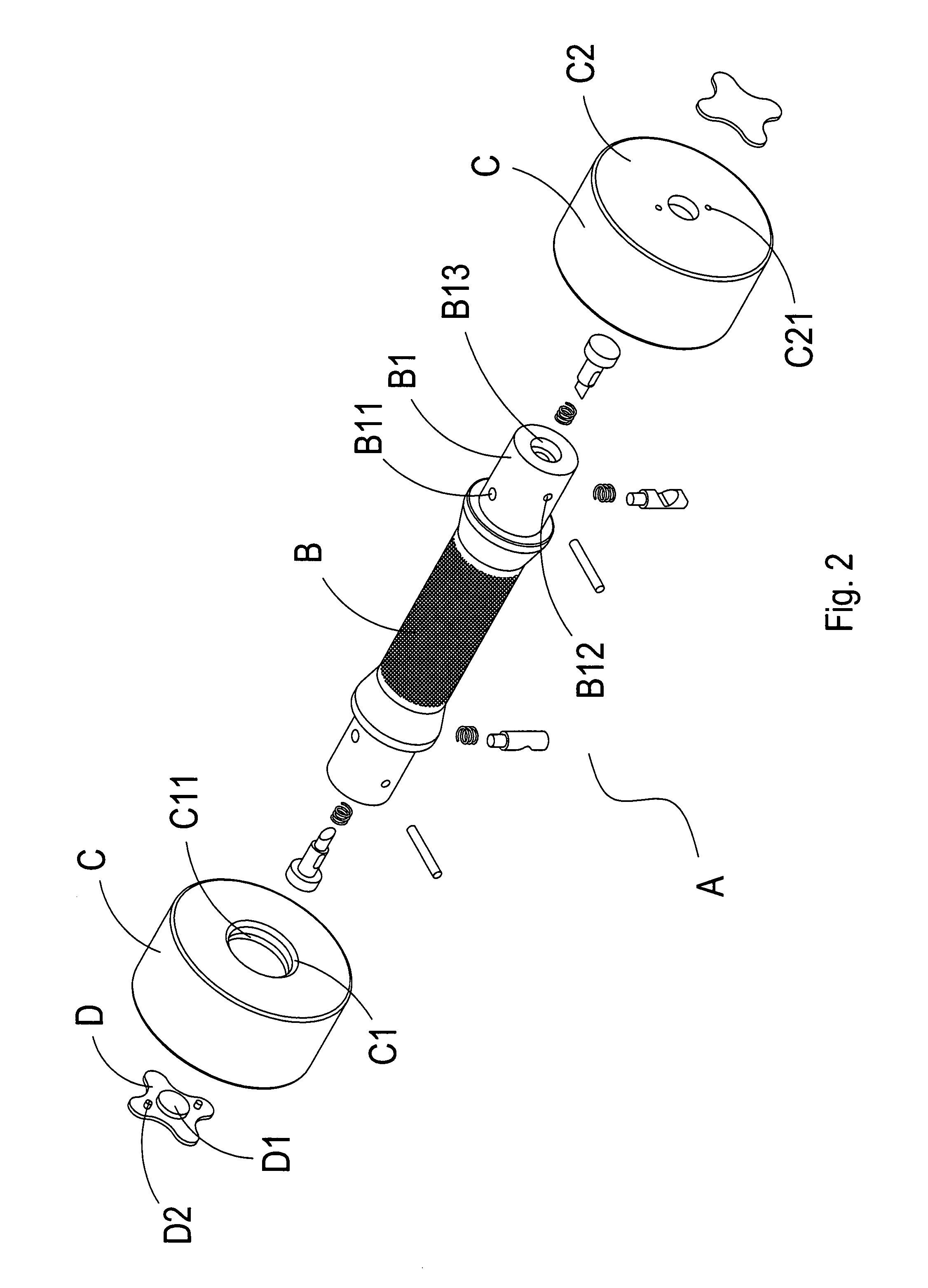
[0021]Referring to FIGS. 1, 2 and 3, which show an external elevational view, an exploded elevational view and a partial exploded view respectively of a preferred embodiment of the present invention, and it can be clearly seen from the drawings that the structure of a dumbbell A comprises a hand grip B, weights C and press operation pieces D. A clamping portion B1 is located on two ends of the hand grip B, and side walls of the clamping portions B1 are respectively configured with clamping holes B11, and clamping columns B111 are respectively located within the clamping holes B11. A spring B112 is mounted on an end of each of the clamping columns B111, and a clamping end B114 is located at the other end. Moreover, the center section of each of the clamping columns B111 is configured with an actuating groove B113. Fixing holes B12 are defined in another side wall of the clamping portions B1 perpendicularly displaced from the clamping holes B11, and a fixing pin B121 is disposed withi...


PUM


Abstract

The present invention relates to an improved dumbbell structure, in which a clamping portion, used for mounting weights, is located on two ends of a hand grip of a dumbbell. A clamping hole, a press operation recess and a fixing hole are defined on each of the clamping portions, and a clamping column is located within each of the clamping holes. A press operation column is disposed within each of the press operation recesses. When force is applied to the press operation column, then the press operation column exerts force on the clamping column, and causes the clamping column to separate from the weight. Accordingly, a user is able to quickly change weights on the dumbbell.

Description

BACKGROUND OF THE INVENTION[0001](a) Field of the Invention[0002]The present invention provides an improved dumbbell structure, and more particularly provides a dumbbell structure with an improved structure that enables quick changing of weights and easy assembly.[0003](b) Description of the Prior Art[0004]Physical fitness activities have already become one of the common leisure activities engaged in by the general public, and apart from forging a strong body, keeping fit can also sculpt a muscular physique. However, because of the usually bulky size and expensive cost of fitness equipment, thus, the general public normally goes to a health club to keep fit. Nevertheless, not every person has the time and the money to spend at a health club, and inasmuch as dumbbells can be easily purchased because of the reasonable market price, thus, the general public will usually purchase dumbbells for use at home. And using the simple dumbbell enables achieving weight training of multiple parts...

Claims


Application Information

Patent Timeline
Patent Type & Authority Patents(United States)
IPC IPC(8): A63B21/072
CPCA63B21/0728A63B21/075
Inventor CHEN, HUNG-LUNG
Owner CHEN HUNG LUNG
Why Eureka
Try Eureka