Microfluidic check-valve embedded in LCP

a microfluidic check valve and check valve technology, applied in mechanical equipment, functional valve types, transportation and packaging, etc., can solve the problems of microcells presenting a number of design challenges, devices tend to have long development times, and are less robus

Active Publication Date: 2006-04-25
HARRIS CORP
View PDF8 Cites 15 Cited by
  • Summary
  • Abstract
  • Description
  • Claims
  • Application Information

AI Technical Summary

Benefits of technology

[0011]The check-valve chamber can be formed without any structure for restricting the range of movement of the plug within the check-valve chamber. Alternatively, the method can include the step of restricting a range of movement of the plug within the check-valve chamber so as to prevent sealing of at least one the outlet port. For example, this can be accomplished by forming from at least one of LCP layers a guide for guiding the plug within the check-valve chamber. The guide can further restrain a range of movement of the plug within the chamber.

Problems solved by technology

Still, microcells present a number of design challenges that will need to be overcome before these devices can be practically implemented.
They also can tend to be less robust.
However, these devices tend to have long development times, are difficult to interface in the macro world, and require more mechanical interfaces.

Method used


Image

  • Microfluidic check-valve embedded in LCP
  • Microfluidic check-valve embedded in LCP
  • Microfluidic check-valve embedded in LCP

Examples


Embodiment Construction

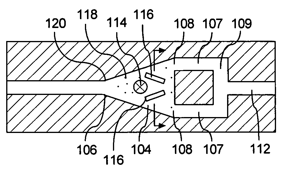
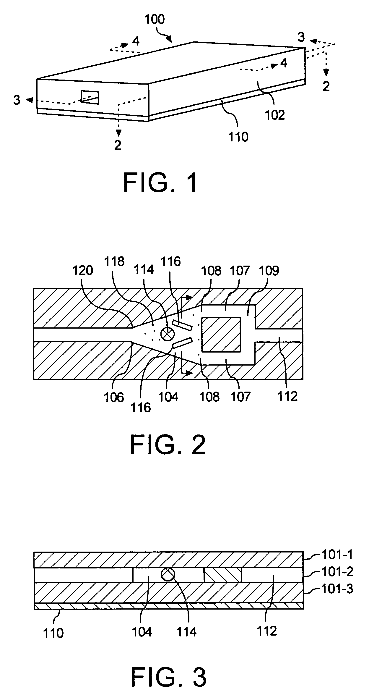
[0026]FIG. 1 shows a first embodiment of a check-valve assembly 100 that is implemented in a substrate 102. The check-valve assembly 100 can be a stand alone device or can be advantageously integrated with a larger system on the substrate. Examples of such larger systems can include fuel cells, micro-motors, and other MEMS type devices. Other examples can include fluid dielectric based devices in the RF field such as antenna elements, matching sections, delay lines, beam steering elements, tunable transmission lines, stubs and filters, variable attenuators, and cavity structures. Still, the invention is not limited to any particular type of device.

[0027]The substrate 102 can be formed from one or more layers of a liquid crystalline polymer (LCP) material. Liquid crystal polymers offer a number of advantages when applied to MEMS structures and microelectronic substrates. For example the material offers excellent moldability in thin sections, a high degree of heat resistance, and is r...


PUM

PropertyMeasurementUnit
thicknessesaaaaaaaaaa
temperatureaaaaaaaaaa

Abstract

Embedded check-valve assembly (100, 600) for integration in a micro-fluidic system. The assembly can include a check-valve chamber (104, 604), an inlet port (106, 606) and an outlet port (108, 608) formed from at least one layer of liquid crystal polymer (LCP) film to form a substrate (102, 602). A plug (114, 614) is disposed within the check-valve chamber.

Description

BACKGROUND OF THE INVENTION[0001]Statement of the Technical Field[0002]The inventive arrangements relate generally to micro-fluidic devices and more particularly to structures and systems for preventing fluid backflow.DESCRIPTION OF THE RELATED ART[0003]Micro-fluidic systems have the potential to play an increasingly important role in many developing technology areas. For example, there has been an increasing interest in recent years in the use of fluid dielectrics for use in RF systems. Likewise, conductive fluids can have use in RF systems as well.[0004]Another technological field where micro-fluidic systems are likely to play an increasingly important role is fuel cells. Fuel cells generate electricity and heat by electrochemically combining a fuel and an oxidant, via an ion-conducting electrolyte. Some types of fuel cells produce waste water as a byproduct of the reaction. This waste water must be transported away from the reaction to be exhausted from the system by a fluid mana...

Claims


Application Information

Patent Timeline
Patent Type & Authority Patents(United States)
IPC IPC(8): F16K15/04
CPCF16K15/04F16K99/0001F16K99/0005F16K99/0057F16K99/0023F16K2099/0082F16K2099/0076F16K2099/008Y10T137/0491Y10T137/6086Y10T137/7904Y10T137/791
Inventor KOENEMAN, PAUL B.PROVO, TERRY M.
Owner HARRIS CORP
Why Eureka
Try Eureka