Display apparatus

a technology of display apparatus and display screen, which is applied in the field of display screen, can solve the problems of deterioration of energy efficiency, and increase of power consumption, and achieve the effect of minimizing the image forming apparatus

Inactive Publication Date: 2012-12-13
SEIKO EPSON CORP
View PDF1 Cites 15 Cited by
  • Summary
  • Abstract
  • Description
  • Claims
  • Application Information

AI Technical Summary

Benefits of technology

[0017]According to this configuration, since an optical system such as lenses for forming parallelized light beams can be simplified and ...

Problems solved by technology

Such a decrease in the time aperture ratio denotes a deterioration in energy effici...

Method used


Image

  • Display apparatus
  • Display apparatus
  • Display apparatus

Examples


first embodiment

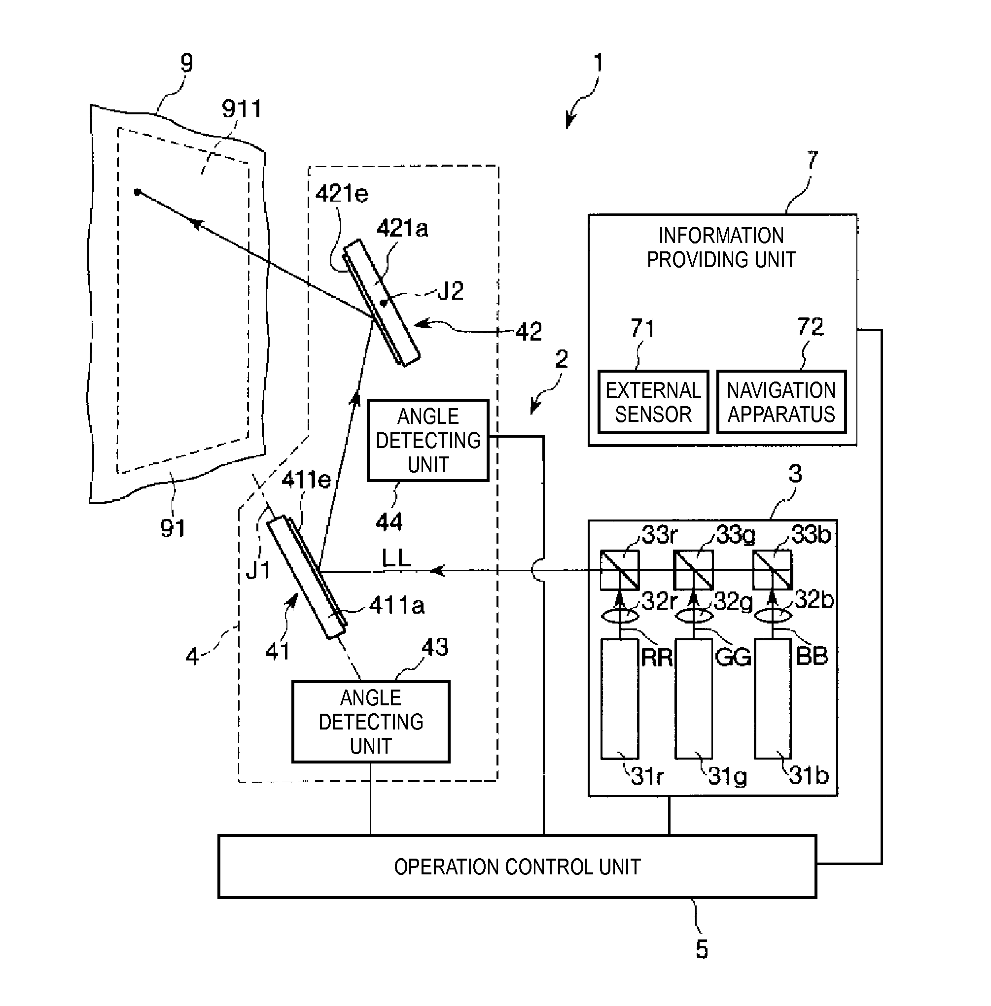
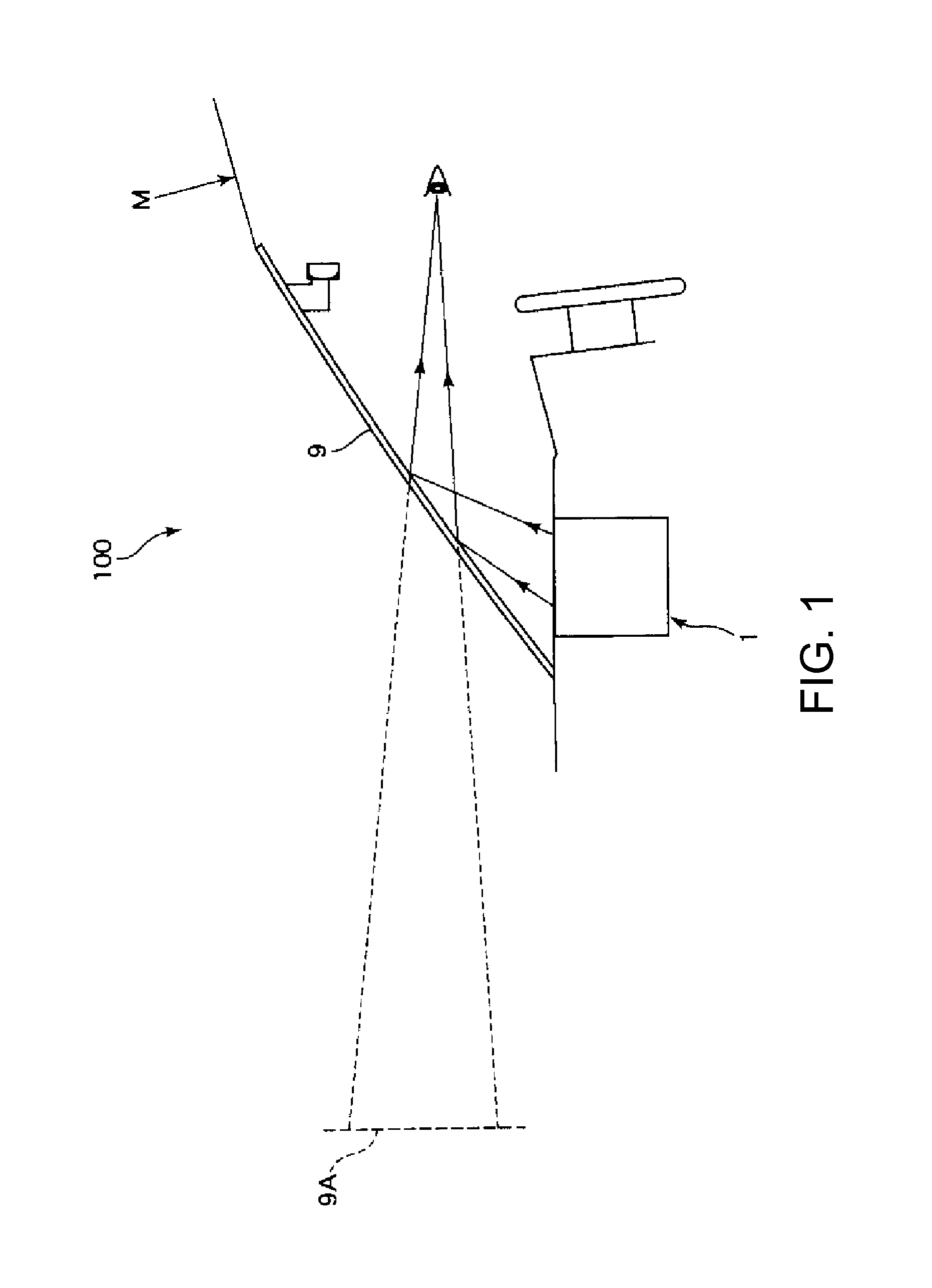
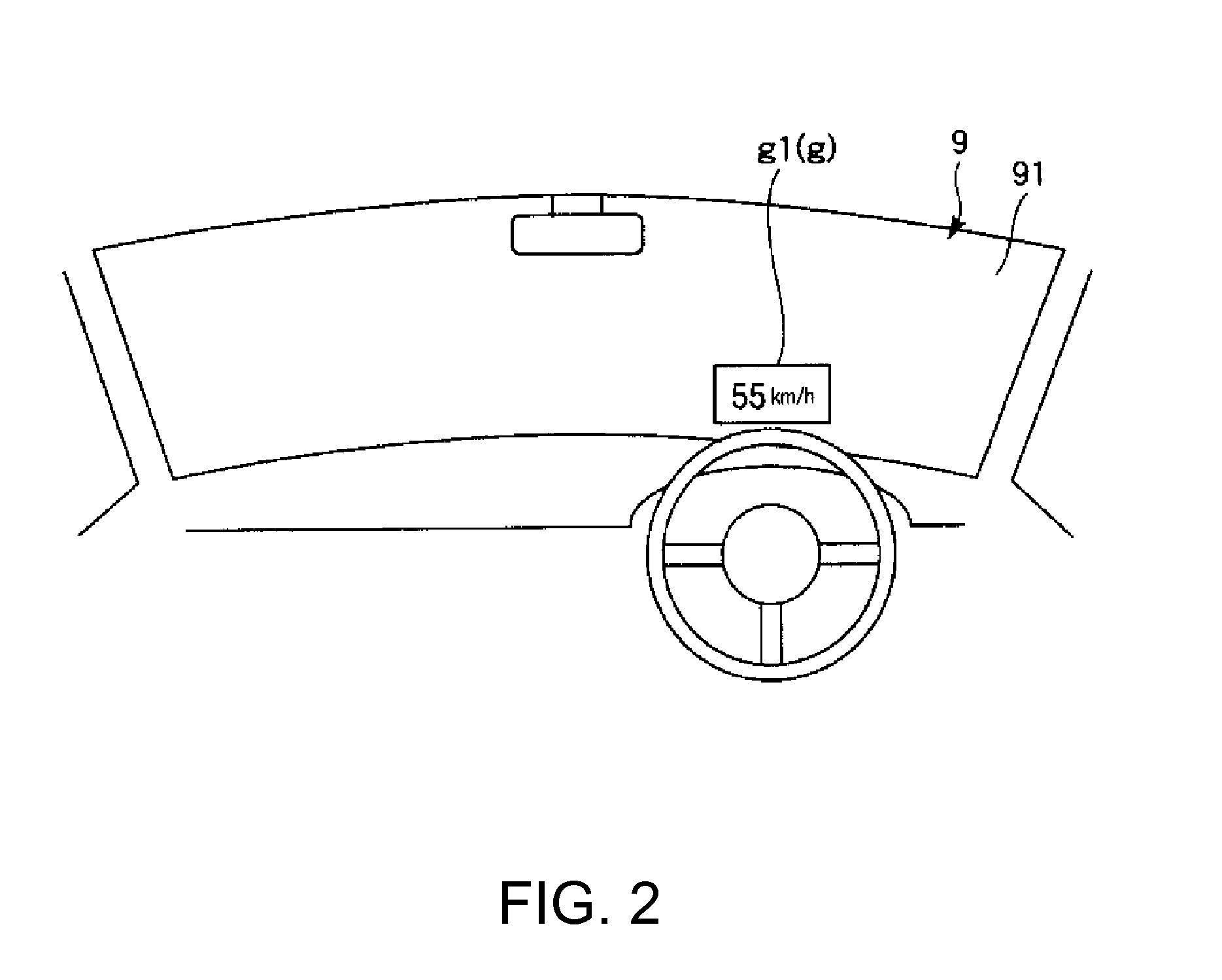
[0035]FIG. 1 is a schematic diagram illustrating a display system (head-up display system) including a display apparatus (head-up display) according to a first embodiment of the invention. FIG. 2 is a schematic diagram illustrating the display system illustrated in FIG. 1. FIG. 3 is a schematic diagram illustrating a schematic configuration of the display apparatus included in the display system illustrated in FIG. 1. FIG. 4 is a partial cross-sectional perspective diagram illustrating a light scanner included in a light scanning unit of the display apparatus illustrated in FIG. 3. FIGS. 5A and 5B are cross-sectional diagrams illustrating operations of the light scanner illustrated in FIG. 4. FIG. 6 is a block diagram illustrating a control system (operation control unit, light scanning unit, and light source unit) of the display apparatus illustrated in FIG. 3. FIGS. 7A and 7B are diagrams illustrating operations of the display apparatus illustrated in FIG. 3 (diagrams illustrating...

second embodiment

[0128]Next, a display apparatus according to a second embodiment of the invention will be described.

[0129]FIGS. 12A and 12B are diagrams illustrating operations of the display apparatus according to the second embodiment of the invention (diagrams illustrating an image renderable region, an image rendering region, and an image). FIGS. 13A and 13B are diagrams illustrating the image renderable region illustrated in FIGS. 12A and 12B.

[0130]Hereinafter, the display apparatus according to the second embodiment will be described concentrating on differences from the aforementioned first embodiment, and description of the same configurations will be omitted.

[0131]The display apparatus according to the second embodiment is substantially the same as the display apparatus according to the first embodiment except that the horizontal length of the image renderable region is not changed and the vertical length of the image renderable region is changed. Furthermore, in FIGS. 12A, 12B, 13A, and 1...

third embodiment

[0142]Next, a display apparatus according to a third embodiment of the invention will be described.

[0143]FIG. 14 is a schematic plan diagram illustrating a light scanner of a projector included in a display apparatus according to the third embodiment of the invention. FIG. 15 is a cross-sectional diagram taken along line XV-XV of FIG. 14. In addition, hereinafter, for the convenience of description, the paper-surface front, paper-surface rear, right, and left sides of FIG. 14 are referred to as “upper”, “lower”, “right”, and “left”, respectively; and the upper, lower, right, and left sides of FIG. 15 are referred to as “upper”, “lower”, “right”, and “left”, respectively.

[0144]Hereinafter, the display apparatus according to the third embodiment will be described concentrating on differences from the aforementioned first embodiment, and description of the same configurations will be omitted.

[0145]The display apparatus according to the third embodiment is substantially the same as the ...


PUM


Abstract

A display apparatus includes: a light emitting unit which emits light; a light scanning unit which includes a light reflector and scans the light in first and second directions; an amplitude changing unit which changes an amplitude of the swing of the light reflector; and a light emitting control unit which adjusts an amount of light of the light emitting unit, wherein the amplitude changing unit allows a first state where the light is scanned in a first region of the display surface and a second state where the light is scanned on the first region and a second region of the display surface is switched, and wherein the light emitting control unit allows an amount of light per unit area of the first region in the first state and an amount of light per unit area of the first region in the second state to be equalized.

Description

BACKGROUND[0001]1. Technical Field[0002]The invention relates to a display apparatus.[0003]2. Related Art[0004]For example, as a head-up display (HUD) which displays images regarding to various types of information of meters, navigation, or the like of a car on a windshield of a vehicle, there is known a head-up display using a display apparatus referred to as a scan type projection system (Laser Scan Projection: LSP) which displays an image by two-dimensionally scanning light beams on a screen (for example, refer to JP-A-2009-137491). In such a display apparatus, a light scanner which one-dimensionally or two-dimensionally scans light beams is installed. For example, the display apparatus disclosed in JP-A-2009-137491 includes a light scanner which two-dimensionally scans light beams by allowing a mirror portion to rotate (swing) around two rotation axes which are perpendicular to each other.[0005]However, with respect to such a display apparatus, since a scanning range (for exampl...

Claims


Application Information

Patent Timeline
IPC IPC(8): G02B26/10G09G5/00G09G5/10
CPCG02B26/10G02B27/01G02B27/0101G02B2027/014G09G2380/10G09G1/07G09G3/002G09G3/003G09G3/025
Inventor ISHIDA, DAISUKEMIZOGUCHI, YASUSHI
Owner SEIKO EPSON CORP
Why Eureka
Try Eureka