Fuel gas heating control equipment and gas turbine power generation facility provided with the fuel gas heating control equipment

a technology of fuel gas heating control and control equipment, which is applied in the direction of turbine/propulsion fuel heating, machines/engines, mechanical equipment, etc., can solve the problems of inability to accurately control and unstable combustion state of combustor, and achieve the effect of restricting the fluctuation rang

Active Publication Date: 2006-06-08
MITSUBISHI POWER LTD
View PDF4 Cites 16 Cited by
  • Summary
  • Abstract
  • Description
  • Claims
  • Application Information

AI Technical Summary

Benefits of technology

[0015] It is an object of the present invention to provide a fuel gas heating control equipment that improves the following capability of the fuel gas temp

Problems solved by technology

As a result, there exists a problem that the combustion gas temperature cannot be stable but fluctuate, which causes the combustion state in a combustor to be unstable.
On the contrary, when the time constant “T” is increased, there e

Method used


Image

  • Fuel gas heating control equipment and gas turbine power generation facility provided with the fuel gas heating control equipment
  • Fuel gas heating control equipment and gas turbine power generation facility provided with the fuel gas heating control equipment
  • Fuel gas heating control equipment and gas turbine power generation facility provided with the fuel gas heating control equipment

Examples


first embodiment

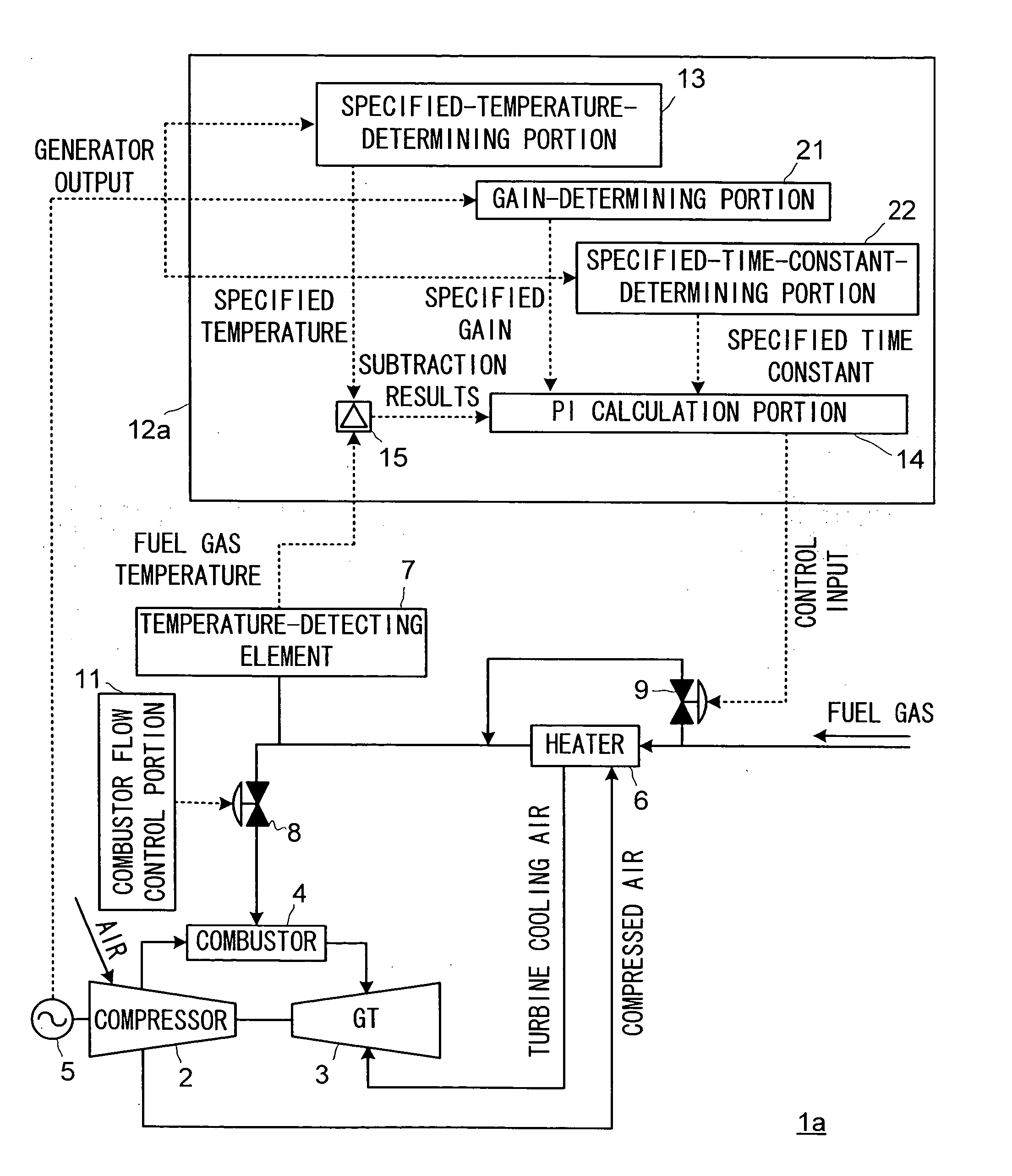
[0029] Referring now to the drawings, a first embodiment of the present invention will be described hereinafter. FIG. 1 is a block diagram showing a construction of a gas turbine power generation facility being provided with a fuel gas heating control equipment in accordance with the present embodiment. In FIG. 1, same portions as in FIG. 10 are provided with same symbols, and the detailed description thereof will be omitted. In addition, movements of a fuel gas and an air are shown with solid lines, and movements of signals of specified values and the like that are to be specified for a block in a subsequent stage are shown with dotted lines.

[0030] A gas turbine power generation facility 1a in FIG. 1 comprises a compressor 2 having an ambient air inhaled and compressed to be high pressure so as to generate a high pressure air; a gas turbine 3 being provided concentrically with the compressor 2; a combustor 4 supplying a combustion gas to a gas turbine 3 in order to rotate the gas ...

second embodiment

[0044] A second embodiment of the present invention will be described hereinafter by referring to the drawings. FIG. 8 is a block diagram showing a construction of a gas turbine power generation facility being provided with a fuel gas heating control equipment in accordance with the present embodiment. In FIG. 8, same portions as in FIG. 1 are provided with same symbols, and the detailed description thereof will be omitted.

[0045] Being compared with a gas turbine power generation facility 1a in accordance with the first embodiment in FIG. 1, a gas turbine power generation facility 1b in FIG. 8 has a different construction of a bypass flow control portion. A bypass flow control portion 12b in accordance with the present embodiment is provided with a first and a second PI calculation portion 31, 32 having a different gain and a different time constant specified in advance in place of the PI calculation portion 13. In addition, are provided a first and a second tracking switch 33, 34 ...


PUM


Abstract

A fuel gas heating control equipment in accordance with the present invention is provided with a gain-determining portion 21 and a time-constant-determining portion 22 which determine values of a gain and a time constant to be used for PI calculations being performed by a PI calculation portion 14. The gain-determining portion 21 specifies a small time constant for the PI calculation portion 14 during load fluctuations when the generator output increases, and specifies a large time constant for the PI calculation portion 14 when the generator output reaches the maximum output. In consequence, during load fluctuations, responsiveness is good and a rapid change in temperature can be followed, so that a fuel gas temperature will not fluctuate in response to a slight change in temperature at the maximum output, thereby achieving a stable fuel gas temperature.

Description

[0001] The present invention is based on the Japanese Patent Application applied as No. 2004-353534 on Dec. 7, 2004. BACKGROUND OF THE INVENTION [0002] 1. Field of the Invention [0003] The present invention relates to a fuel gas heating control equipment of a gas turbine, and especially, relates to fuel gas heating control equipment which controls the flow rate of a fuel gas passing through a heater being installed to a fuel gas system. In addition, the present invention relates to a gas turbine power generation facility being provided with the fuel gas heating control equipment as aforementioned. [0004] 2. Description of the Prior Art [0005] A conventional gas turbine has a heater installed to a stage preceding a combustor in order to enhance combustion efficiency of a fuel. (See the Japanese Patent Application Laid-Open No. H11-236824.) [0006]FIG. 10 is a diagram showing an example of a fuel system of a conventional general gas turbine power generation facility. In a gas turbine p...

Claims


Application Information

Patent Timeline
IPC IPC(8): F02C1/00
CPCF02C7/185F02C7/224
Inventor TANAKA, SATOSHIMORIMOTO, TOSHIMITSU
Owner MITSUBISHI POWER LTD
Why Eureka
Try Eureka