Ultrasonographic device

a technology of ultrasound transducer and diaphragm, which is applied in the field of ultrasound transducer, can solve the problems of electro-acoustic conversion efficiency drift, unstable charged state of insulation film, and inability to capture charge on the surface of compound layer, so as to prevent lateral resolution of image and dynamic range from dropping, and to suppress deterioration

Inactive Publication Date: 2009-12-10
HITACHI MEDICAL CORP
View PDF9 Cites 15 Cited by
  • Summary
  • Abstract
  • Description
  • Claims
  • Application Information

AI Technical Summary

Benefits of technology

[0010]According to the present invention, drift of transducer properties being a main cause of variation in transducer sensitivities can be suppressed more compared with conventional transducers. Further, in an aspect of the present invention, there is provided an ultrasonographic device capable of suppressing deterioration in a transmit / receive ultrasound beam and preventing a lateral resolution of an image and a dynamic range from dropping.

Problems solved by technology

However, charges can be trapped not only on a surface of the compound layer but also in the compound layer by controlling the quantity of crystal defects.
However, in reality, the charged state of an insulation film is unstable and charges drift, while the insulation film is used.
Thus, there arises a problem that electro-acoustic conversion efficiency drifts, the efficiency being the most basic property as an electro-acoustic transducer.
When the conversion efficiency can hardly be stabilized even in a range of a satisfactory level, a major obstacle occurs with a practical use of insulation layers as transducers.
The effect causes not only drift of the sensitivity of the whole electro-acoustic converter, but also a risk that, if the electro-acoustic conversion properties of the transducers constituting an array converter drift unevenly, the acoustic noise level is extremely raised when operation for forming transmit and receive beams is performed by the whole electro-acoustic converter.
Accordingly, particularly in order to construct an array converter using charge accumulating type diaphragm electro-acoustic transducers and raise the properties to a practical level, overcoming the problem of drifting is a second significant issue along with the first significant issue of obtaining a large electro-acoustic conversion efficiency.

Method used


Image

  • Ultrasonographic device
  • Ultrasonographic device
  • Ultrasonographic device

Examples


Embodiment Construction

[0022]Embodiments of the present invention will be described below in detail with reference to the accompanying drawings.

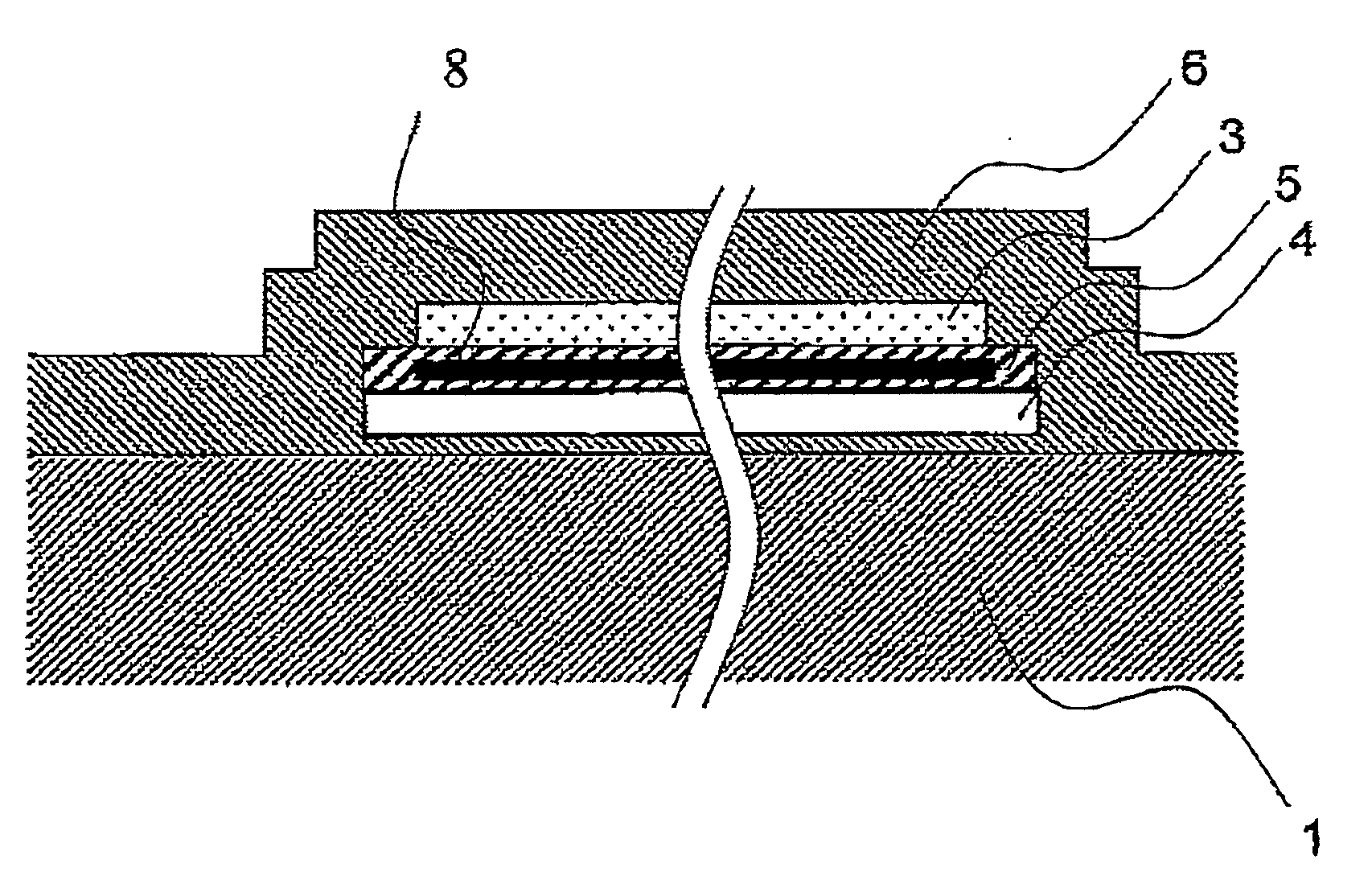
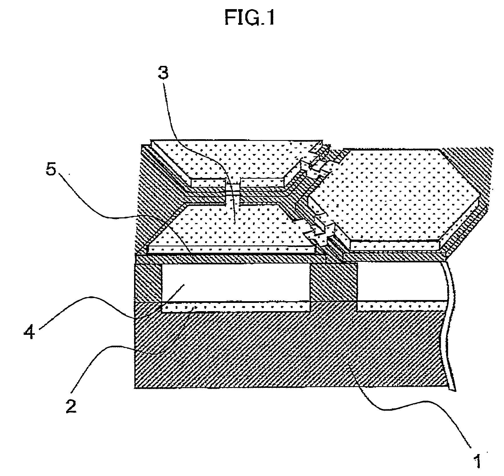
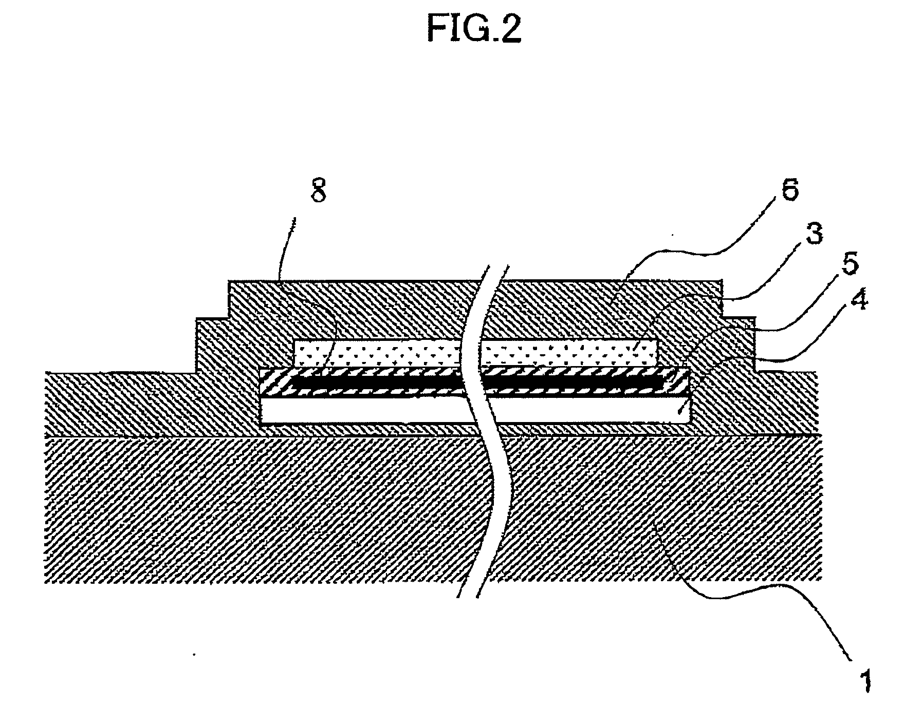
[0023]In a typical basic structure of an ultrasound transducer using diaphragm electro-acoustic transducers, as shown in FIG. 1, a bottom electrode 2 and a top electrode 3 form a capacitor, the electrodes 2 and 3 being provided respectively on a substrate 1 and a diaphragm 5, with a cavity 4 therebetween. When a voltage is applied between the electrodes 2 and 3, charges are induced in both the electrodes 2 and 3 respectively with opposite polarities, and attract each other, thus the diaphragm 5 being displaced. If the outside of the diaphragm 5 is in contact with water or an organism at this time, a sound wave is radiated into the medium. This is the principle of electro-mechanical conversion in transmission. On the other hand, if a DC bias voltage is applied to induce a certain amount of charges in the electrodes 2 and 3, and oscillation is forcibly applied to th...


PUM

PropertyMeasurementUnit
inner diameteraaaaaaaaaa

Abstract

The receive sensitivity of an ultrasound array transducer structured with a diaphragm electro-acoustic transducer (101) being a basic unit is affected by change in a charge amount with elapsed time due to leakage or the like, which causes drift of the primary beam sensitivity, degradation in the acoustic SN ratio due to a rise in the acoustic noise level, and degradation in the directivity of an ultrasound beam. To addressing this problem, a charge controller (charge monitor 211) is provided to control charge in an electro-acoustic transducer (101). A charge monitoring section (102) monitors the change in the charge amount. When change in the charge amount is small, transmit sensitivity or receive sensitivity is calibrated by a controller (104) by, for example, multiplying a receive signal by a calibration coefficient corresponding to the change amount. Further, when the change in the charge amount is large, for example, charges can be re-emitted from a charge emitter (103). The series of operations is controlled by the controller (104), and thus sensitivity variation caused by difference in the changes with elapsed time, particularly between the plural transducers, is calibrated.

Description

TECHNICAL FIELD[0001]The present invention relates to a transducer for transmitting / receiving ultrasound, and particularly relates to a silicon-based diaphragm ultrasound transducer.BACKGROUND ART[0002]Although most ultrasound transducers for practical use are still piezoelectric ceramic ultrasound transducers (PZT), a fine diaphragm transducer has been researched and developed since the 1990's to take the place of the ceramic ultrasound transducer by the use of semiconductor micro-processing technology, such as represented by the technology disclosed on pages 1241-1244 of “Proceedings of 1994 IEEE Ultrasonics Symposium.”[0003]Although acoustic impedance is constant as a physical property value unique to a material in the case of a conventional piezoelectric transducer using PZT, pseudo-acoustic impedance of a diaphragm structure reflects not only a material but also a structure. Thus, the diaphragm transducer has a degree of freedom in design suitable for a subject.[0004]Recently, ...

Claims


Application Information

Patent Timeline
Patent Type & Authority Applications(United States)
IPC IPC(8): G01N29/34H02N1/08
CPCA61B8/08A61B8/4281G01S15/00B06B1/0292G01N29/2431A61B8/4483
Inventor AZUMA, TAKASHIUMEMURA, SHINICHIRONAGATA, TATSUYAFUKUDA, HIROSHIMACHIDA, SHUNTAROMINE, TOSHIYUKI
Owner HITACHI MEDICAL CORP
Why Eureka
Try Eureka