[0028]In the solar battery module device according to the present invention, the solar battery module can be mounted on the installing member and installed on the sloping roof by fixing the installing member on the roof, then fitting the top-side end part serving as one side of the rectangular shape of the solar battery module from the lower side in the sloping direction of the roof in the engagement part of the upper frame in the installing member, and then mounting the fixing cover on the lower frame with the bottom-side end part serving as the opposite side of the rectangular shape of the solar battery module placed on the placing surface of the lower frame to fix the bottom-side end part on the placing surface. Therefore, a plurality of installing members corresponding to a required number of solar battery module devices, for example, are previously fixed on the roof. The solar battery module can be individually mounted on the installing member at an arbitrary position at an arbitrary time.
[0029]Therefore, it is possible to
mount the solar battery modules on the installing members in order from the
ridge to the edge of
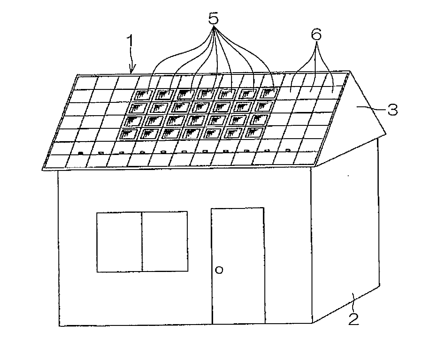
eaves of the sloping roof, for example, which was impossible in the conventional solar battery module device installed in the same manner as the normal roofing material. The chances that a worker must get on the solar battery module can be significantly reduced to improve the safety of installation operations and prevent the solar battery module from damage by suitably setting the order in which the solar battery modules are mounted in conformity with the shape or the like of the roof.
[0030]Furthermore, the solar battery module at the arbitrary position can be individually removed from the installing member in a procedure opposite to the foregoing procedure without removing the other solar battery modules. Therefore, operations in a case where misconnection is found in a test during or after installation, for example, or a case where a failure or the like is found at the time of maintenance and inspection operations of the photovoltaic power generating system can be also significantly simplified.
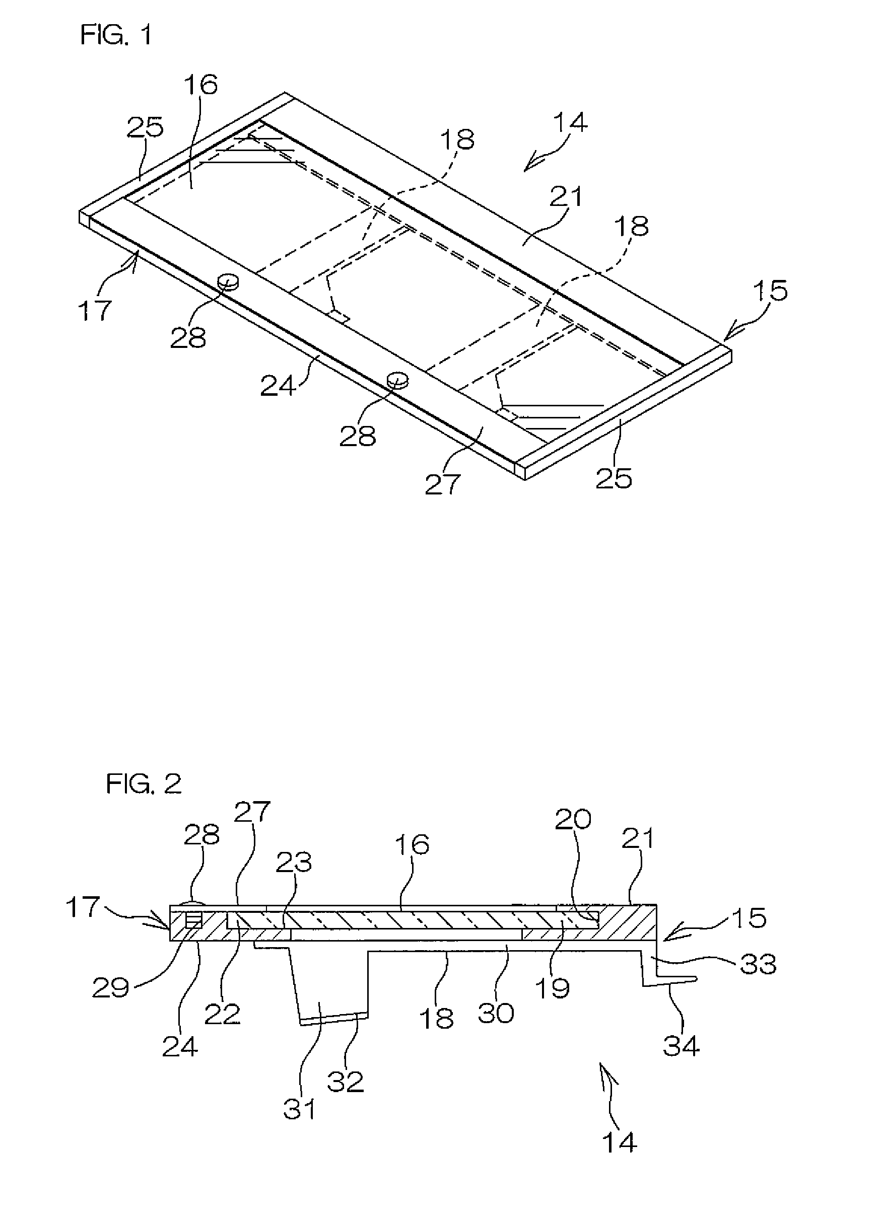
[0031]When the lower frame in the installing member has the flat plate-shaped extended part extended in a slopingly downward direction of the surface of the solar battery module to be mounted on the lower side in the sloping direction of the roof, and the fixing cover has the flat plate-shaped mounting part overlapped with the extended part and mounted thereon and the fixing part abutted against the end surface and the upper surface of the bottom-side end part of the solar battery module for fixing the bottom-side end part to the lower frame with the mounting part mounted on the extended part, the solar battery module can be mounted on the installing member more reliably without producing backlash or the like.
[0032]That is, when the mounting part of the fixing cover is mounted on the extended part extended in a slopingly downward direction of the surface of the solar battery module of the lower frame with the fixing part of the fixing cover abutted against the end surface and the upper surface of the bottom-side end part of the solar battery module, a fixing force directed downward in the thickness direction, i.e., toward the placing surface of the lower frame can be applied to the bottom-side end part of the solar battery module from the upper surface thereof, and a fixing force directed toward the upper side in the sloping direction of the roof, i.e., toward the upper frame can be also applied to the end part from the end surface thereof.
[0033]Therefore, the solar battery module mounted on the installing member can be prevented from backlash of the solar battery module and more reliably mounted, for example. The deterioration of the solar battery module due to the occurrence of
corrosion, for example, can be reliably prevented by preventing a protective film such as an alumite layer, a plating layer, or a clear coat layer for covering a surface of a frame formed of an aluminum
alloy or the like, of the solar battery module from damage and chipping and
thinning due to backlash of the solar battery module against the installing member, for example.

