Pedicle screw assembly and methods therefor

a technology of pedicle screw and assembly, which is applied in the field of spinal fixation devices, can solve the problems of reducing nerve function, fixation devices, extreme pain of patients who suffer from such conditions, etc., and achieves the effect of enhancing the compactness of the assembly and lowering the overall silhou

Inactive Publication Date: 2005-02-22
STRYKER SPINE
View PDF27 Cites 264 Cited by
  • Summary
  • Abstract
  • Description
  • Claims
  • Application Information

AI Technical Summary

Benefits of technology

In accordance with certain preferred embodiments of the present invention, a stabilizing assembly used for stabilizing a spinal column includes a fastener having an upper end and a head at the upper end, and at least one anchoring element between the upper and lower ends thereof. The head of the fastener preferably includes a center, an underside including a first radial surface and a top side including a second radial surface, the first radial surface defining a first radius from the center of the head and the second

Problems solved by technology

Patients that suffer from such conditions usually experience extreme and debilitating pain, as well as diminished nerve function.
However, as will be set forth in more detail below, there are some disadvantages associated with current fixation devices.
Surgeons have encountered considerable difficulty when attempting to insert spinal fixation devices such as those disclosed in the above-mentioned '388 patent.
This is because the U-shaped heads of adjacent screws are often out of alignment with one another due to curvature in spines and the different orientations of the pedicles receiving the screws.
These problems weaken the strength of the assembly and result in significantly longer operations, thereby increasing the likelihood of complications associated with surgery.
However, the above-mentioned patents do not solve all of the deficiencies of fixation devices such as

Method used


Image

  • Pedicle screw assembly and methods therefor
  • Pedicle screw assembly and methods therefor
  • Pedicle screw assembly and methods therefor

Examples


Embodiment Construction

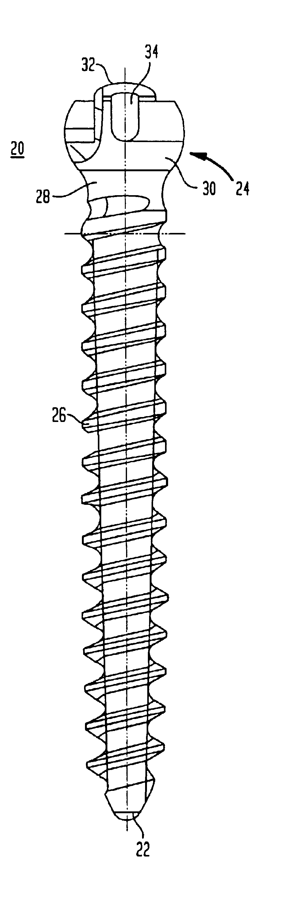
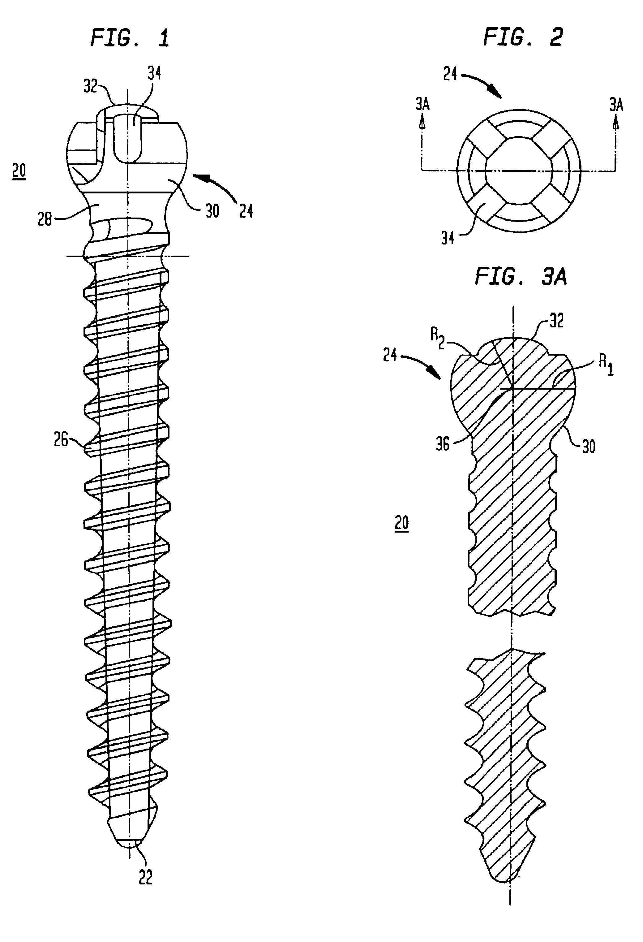
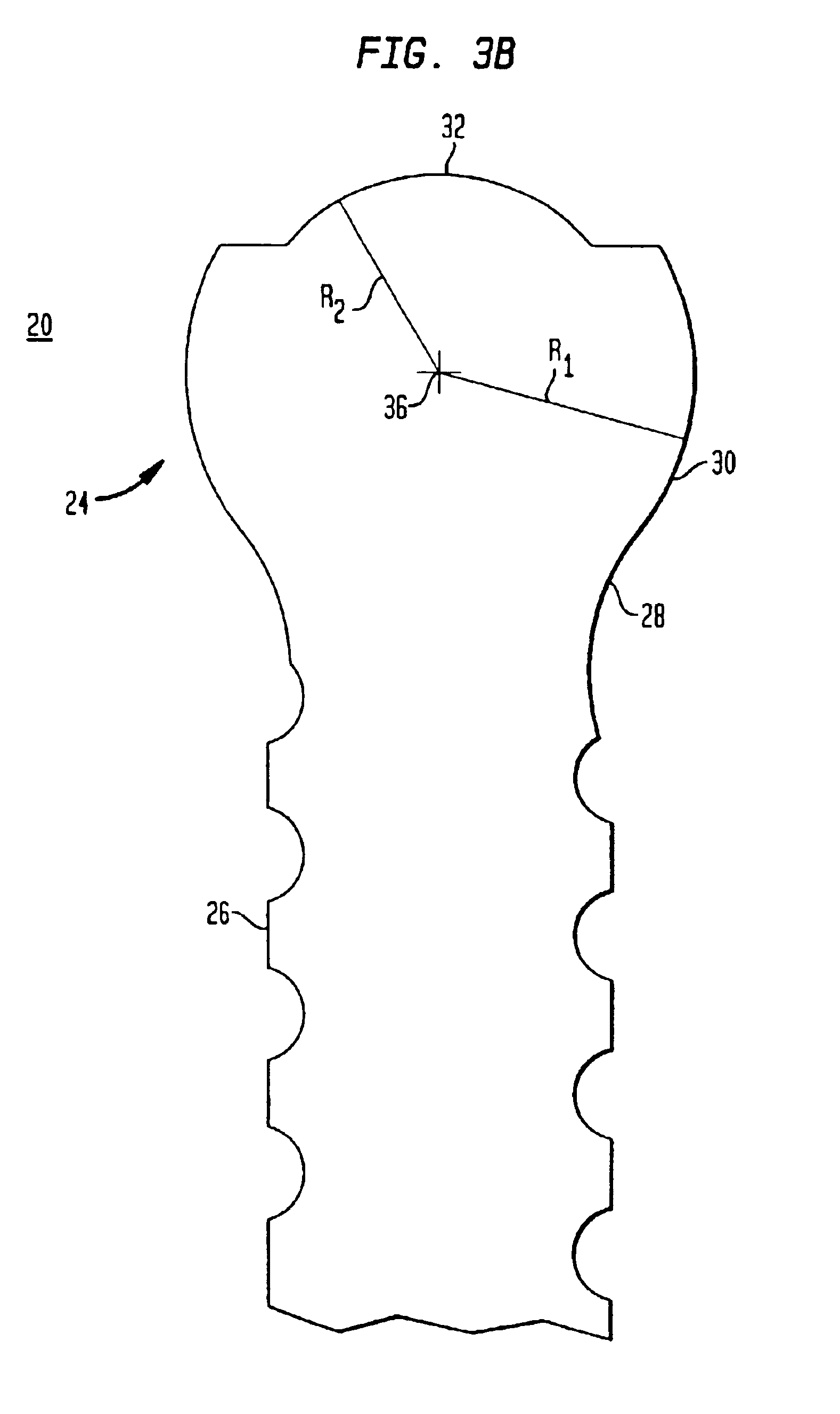
Referring to FIG. 1, in accordance with certain preferred embodiments of the present invention, a pedicle screw assembly includes a fastener 20, such as a screw fastener having a tip end 22 for insertion into bone and a head 24 at an upper end thereof. The screw fastener 20 preferably has external screw threads 26 that extend between the tip end 22 and screwhead 24. The screw threads 26 terminate at a neck 28 preferably located between screwhead 24 and an upper end of the screw threads 26. The neck 28 desirably has a concave surface having a diameter that is less than the diameter of the screw threads. The reduced diameter neck 28 allows the screw fastener 20 to pivot and rotate through a broader range of motion, as will be described in more detail below. The screw fastener, including the external threads 26, neck 28 and screwhead 24, are preferably made of a non-organic material that is durable and that can be implanted in a human body, such as titanium or stainless steel.

Referring...


PUM


Abstract

A method for stabilizing a spine includes providing a coupling element having upper and lower ends, a rod receiving opening adapted to receive an elongated stabilizing rod, a bore extending through the lower end and a conical-shaped seat surrounding the bore adjacent the lower end; providing a fastener having upper and lower ends, a head having a radial surface, and at least one anchoring element between the lower end of the fastener and the head; assembling the fastener with the coupling element so that the lower end of the fastener passes through the bore of the coupling element and the radial surface of the head engages the conical-shaped seat. The method also includes anchoring the fastener to bone; moving the coupling element relative to the fastener for capturing the elongated stabilizing rod in the rod receiving opening; and urging the captured stabilizing rod toward the head of the fastener so that the rod contacts the head and forces the radial surface of the head against the conical-shaped seat of the coupling element for locking the coupling element from further movement relative to the fastener.

Description

BACKGROUND OF THE INVENTIONThe present invention relates generally to spinal fixation devices and more specifically relates to a pedicle screw assembly having a low profile and having an improved screwhead / coupling element interface for locking the assembly.The spinal column is a highly complex system of bones and connective tissues that provides support for the body and protects the delicate spinal cord and nerves. The spinal column includes a series of vertebrae stacked one atop the other, each vertebral body including an inner or central portion of relatively weak cancellous bone and an outer portion of relatively strong cortical bone. Situated between each vertebral body is an intervertebral disc that cushions and dampens compressive forces experienced by to the spinal column. A vertebral canal containing the spinal cord and nerves is located behind the vertebral bodies.There are many types of spinal column disorders including scoliosis (abnormal lateral curvature of the spine),...

Claims


Application Information

Patent Timeline
IPC IPC(8): A61B17/88A61B17/70A61B17/58G06F17/21
CPCA61B17/7037A61B17/7032A61B17/7082G06Q10/107A61B17/58A61B2017/564
Inventor MARTIN, GREGCROZET, YVESKELLY, WILLIAM J.
Owner STRYKER SPINE
Why Eureka
Try Eureka