Chute for Laser Sintering Systems

a laser sintering and sintering chamber technology, applied in auxillary shaping apparatus, additive manufacturing with solid and fluid, manufacturing environment conditioning, etc., can solve the problems of adversely affecting the final part, adversely affecting the surface, rough surface or other imperfections in the final part, etc., to reduce the likelihood of surface features, and improve the effect of part quality

Active Publication Date: 2014-09-18
3D SYST INC
View PDF8 Cites 83 Cited by
  • Summary
  • Abstract
  • Description
  • Claims
  • Application Information

AI Technical Summary

Benefits of technology

[0006]The various embodiments of the present invention address the above needs and achieve other advantages that improve the part quality and reduce the need to dispose of sinterable powder. One embodiment of the present invention includes methods for applying the powder layer to reduce the likelihood of surface features that can lead to reduced part strength or accuracy and that improve the density of the powder in the layer. Certain embodiments use a “two pass” approach (also called “dual APL” (APL=Apply Powder Layer)) to laying down a single layer of powder (with a counter-rotating roller or other powder distributing device) by distributing a layer of powder in a first pass similar to traditional (prior art) applications of a powder layer, but then, unlike the prior art, the roller is moved back in a second pass that distributes residual powder to fill gaps and level the surface of the powder layer. In order to distribute the residual powder from the first pass, a return powder device (such as a piston) is provided on an opposite side of the part bed (the area where the powder is laser sintered) from where the powder is deposited by a hopper. The return powder device is lowered to allow the residual powder to pass beneath the roller and is raised after the roller has passed so that the roller can distribute the residual powder. Any residual powder that remains after the second pass is deposited into a powder return shoot on the side of the part bed. By using the two pass technique, the powder layers have improved uniformity and better densification for more accurate laser sintering.
[0008]Still further embodiments of the present invention include a chute device for the deposition of powder between the roller and part bed with little or no dust being created. The chute device of certain embodiments is a rigid slot below the hopper that extends to near the surface the powder is being deposited to minimize the distance the powder must fall, thus minimizing the amount of dust created. The chute device is rotatable so that it does not interfere with the movement of the roller. The chute is also positioned so that it does not block the laser beam from the part bed. In some embodiments, the chute includes heater elements to preheat the powder to be deposited.
[0009]Other embodiments of the present invention include a roller heater positioned below or proximate the stationary roller position (where the roller is parked during the laser scanning operation) so that the roller surface may be heated to a desired temperature. The roller heater may alternatively comprise a chute heater that pre-heats powder in the chute and also heats the roller surface. The roller may be rotated so that the roller heater evenly heats the surface of the roller to prevent temperature gradients on the roller surface which can lead to undesirable adhesion of powder to some, but not all, surfaces of the roller which results in powder being slung behind the roller which further results in uneven powder surfaces that ultimately result in rough surfaces or other imperfections in the final part.
[0010]Still further embodiments of the present invention include an air scrubber that cleans the air (consisting primarily of nitrogen) within the build chamber. The air is cooled through the scrubber to assist with the removal of airborne contaminants by the filter(s). The exhaust air of the scrubber that is recirculated back into the build chamber is exhausted into a heater bracket that retains the heaters (that heat the powder by radiation and convection) in order to (i) reheat the relatively cool recirculated air and (ii) cool the heater brackets and heaters so that the heaters are not overheated. The heater brackets have exhaust holes along an outwardly facing surface so that the air is circulated back into the chamber in a way that does not create significant turbulence or other undesirable air flow that could adversely affect the laser sintering process. Therefore, the various embodiments of the present invention provide significant improvements to the laser sintering system and process that result in improved part quality and reduced waste material.

Problems solved by technology

The build chamber of a laser sintering system is typically very hot and includes fumes and dust that can adversely affect surfaces.
The roller may be rotated so that the roller heater evenly heats the surface of the roller to prevent temperature gradients on the roller surface which can lead to undesirable adhesion of powder to some, but not all, surfaces of the roller which results in powder being slung behind the roller which further results in uneven powder surfaces that ultimately result in rough surfaces or other imperfections in the final part.

Method used


Image

  • Chute for Laser Sintering Systems
  • Chute for Laser Sintering Systems
  • Chute for Laser Sintering Systems

Examples


Embodiment Construction

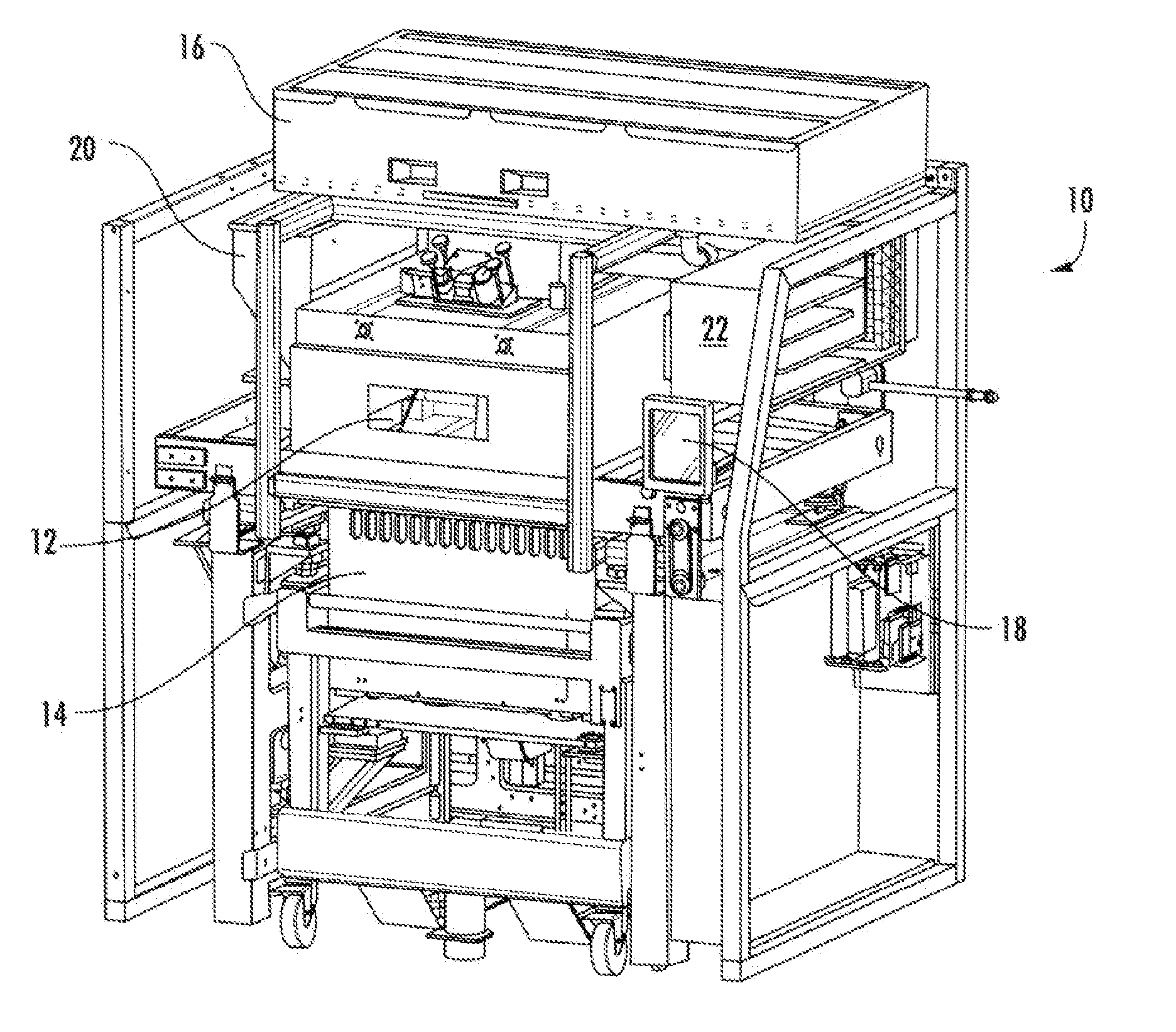
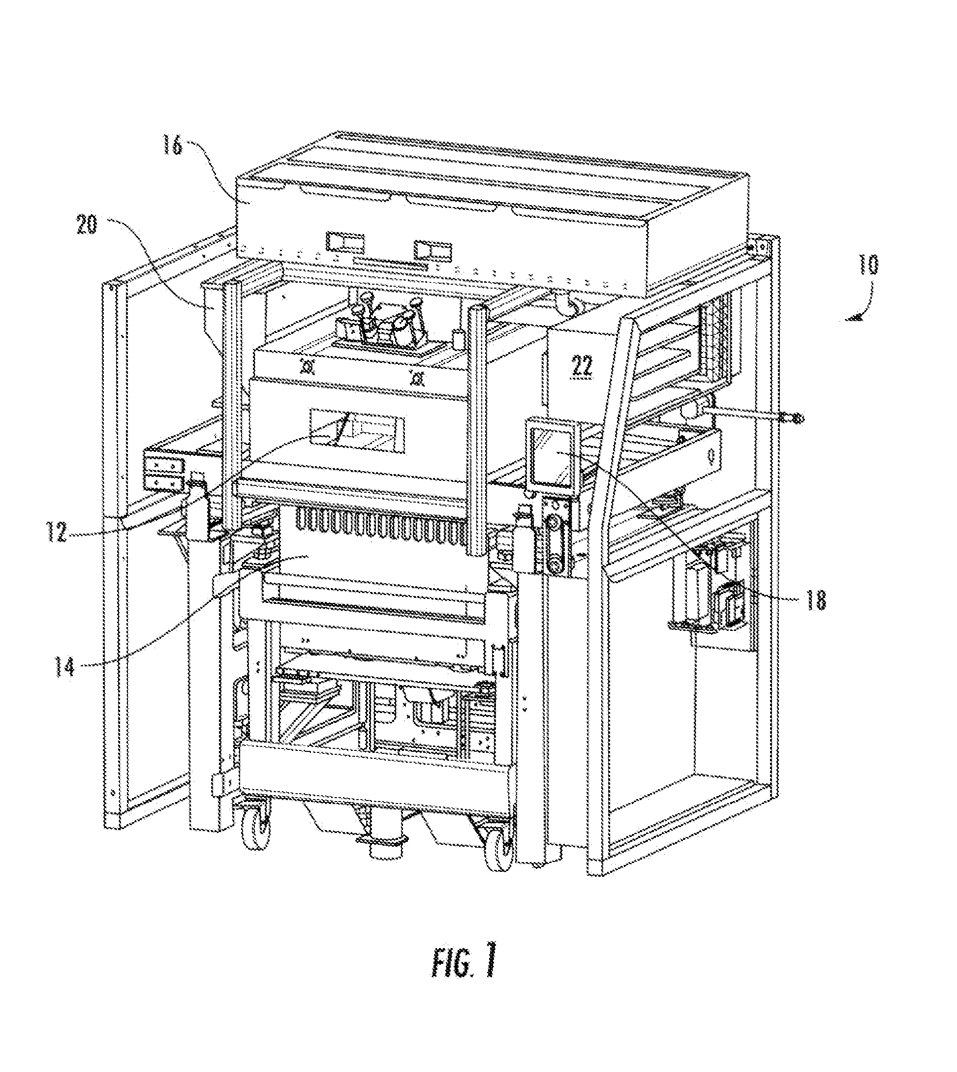
[0027]The present invention now will be described more fully hereinafter with reference to the accompanying drawings, in which some, but not all embodiments of the invention are shown. Indeed, the invention may be embodied in many different forms and should not be construed as limited to the embodiments set forth herein; rather, these embodiments are provided so that this disclosure will satisfy applicable legal requirements. Although apparatus and methods for providing improved part quality and reduced powder disposal are described and shown in the accompanying drawings with regard to specific types of laser sintering systems, it is envisioned that the functionality of the various apparatus and methods may be applied to any now known or hereafter devised powder fusing systems in which it is desired to created three dimensional objects (parts) out of powder based upon digital data representing the part to be made. Like numbers refer to like elements throughout.

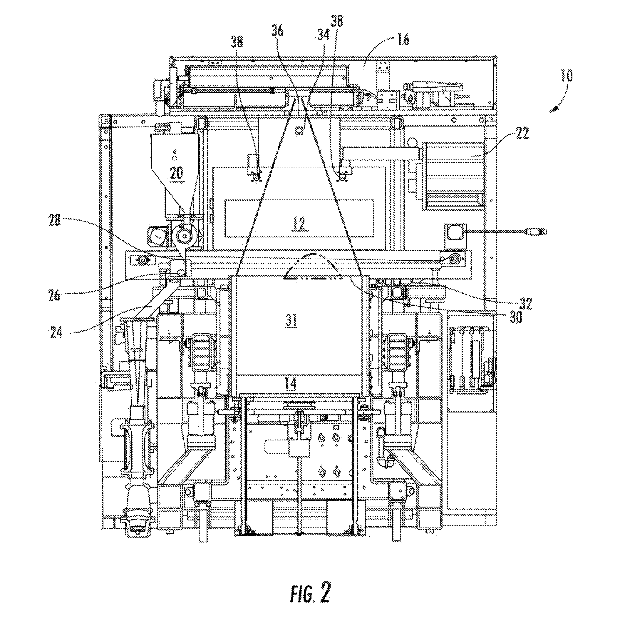
[0028]With reference t...


PUM

PropertyMeasurementUnit
laser power measurementaaaaaaaaaa
poweraaaaaaaaaa
mechanical propertiesaaaaaaaaaa

Abstract

There is provided improved laser sintering systems that increase the powder density and reduce anomalies of the powder layers that are sintered, that measure the laser power within the build chamber for automatic calibration during a build process, that deposit powder into the build chamber through a chute to minimize dusting, and that scrubs the air and cools the radiant heaters with recirculated scrubbed air. The improvements enable the laser sintering systems to make parts that are of higher and more consistent quality, precision, and strength, while enabling the user of the laser sintering systems to reuse greater proportions of previously used but unsintered powder.

Description

CROSS REFERENCE TO RELATED APPLICATION[0001]The present application claims priority pursuant to 35 U.S.C. 119(e) to U.S. Provisional Application Ser. No. 61 / 793,870, filed Mar. 15, 2013.FIELD OF THE INVENTION[0002]The present invention is related to laser sintering systems, and more particularly, to laser sintering systems apparatus and methods for improving part quality and reduced disposal of used, unsintered powder.BACKGROUND OF THE INVENTION[0003]Laser sintering is one form of additive manufacturing that fabricates three-dimensional objects from digital data. As known in the art, laser sintering heats layers of powder, typically a polymer or a metal, with a laser to cause the powder particles to fuse to one another in predetermined patterns to define the cross-sectional layers of the object being fabricated. Such techniques are disclosed in U.S. Pat. Nos. 4,863,538; 5,155,321; 5,252,264; 5,352,405; 6,815,636; 7,569,174; and 7,807,947, the disclosures of which are incorporated by...

Claims


Application Information

Patent Timeline
Patent Type & Authority Applications(United States)
IPC IPC(8): B29C67/00
CPCB29C67/0077B22F3/004B29C64/153B29C64/165B29C64/357B29C64/329B29C64/218B29C64/205B29C64/236B29C64/364B29C64/371B29C64/295B22F10/28B22F12/13B22F10/73B22F12/52B22F10/36B22F12/20B22F12/63B29C64/35Y02P10/25B33Y10/00B33Y30/00B28B1/001B29K2071/00B29K2077/00B29K2105/251
Inventor CULLEN, DAVID H.HIDALGO, RAFAEL ENRIQUE
Owner 3D SYST INC
Why Eureka
Try Eureka