Surgical compression clips

a compression clip and surgical technology, applied in the field of surgical compression clips, can solve the problems of affecting the peristalsis of the sutured area, and common post-operative complications

Inactive Publication Date: 2007-09-13
NITI SURGICAL SOLUTIONS
View PDF11 Cites 259 Cited by
  • Summary
  • Abstract
  • Description
  • Claims
  • Application Information

AI Technical Summary

Benefits of technology

[0040]In another embodiment of the present invention, the assembly further includes a wire extending between the second end portion of each of the two compression elements. The wire is releasably connected to the latch member and has an extension extending via the second end portion of the second compression element through the first compression element. The extension is operative to draw the wire taut when tissue is positioned between the two compressing elements. The taut wire thereby prevents the tissue from moving out from between the pair of compression elements while the clip assembly is brought to its closed position.

Problems solved by technology

Another disadvantage of this technique is that post-operative complications are common.
Further, suturing an organ results in lack of smoothness of the tissue therein, which, when the sutured organ is part of the gastrointestinal tract, hampers peristalsis in the sutured area.
Finally, suturing is both labor and time consuming.
However, after healing, metal staples remain in place along the perimeter of the suture, which reduces elasticity of the junction and adversely affects peristalsis when the sutured organ is part of the gastrointestinal tract.
These complications often lead to strictures and inflammatory reactions to the foreign bodies left behind.
Staples also often lead to undesired leakage of blood and other body liquids into the region of resected tissue further resulting in severe infection.
Additionally, stapling mechanisms generally are relatively large and fairly rigid, limiting the maneuverability of an endoscope used in conjunction with the stapling mechanism.
This lack of maneuverability restricts an endoscopic approach to many locations within the body.
Moreover, when used in the GI tract they are often self-evacuated.
A major disadvantage of known clips is that they permit compression of only approximately 80-85% of the junction perimeter, thus requiring additional manual sutures, which reduce the integrity of the seal of the junction during the healing period and its elasticity during the post-operative period.
Furthermore, this additional suturing is problematic inasmuch as it has to be carried out across a joint which includes a portion of the clip, thereby rendering difficult the sealing and anastomosis of the organ portions.
This can lead to the clip disengaging from the closure site before closure is complete and scar tissue mature.
Typically, clips do not necessarily have a securing mechanism against slipping off the tissue.
Clips as currently designed may also affect the maneuverability of an endoscope.

Method used


Image

  • Surgical compression clips
  • Surgical compression clips
  • Surgical compression clips

Examples


first embodiment

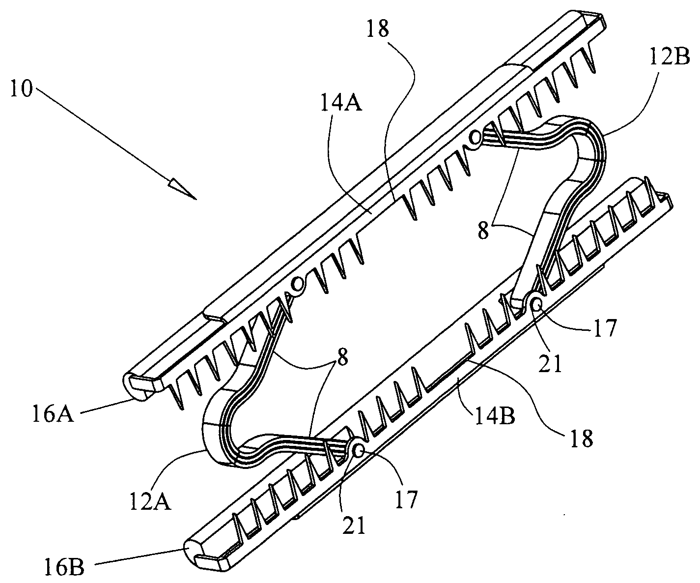
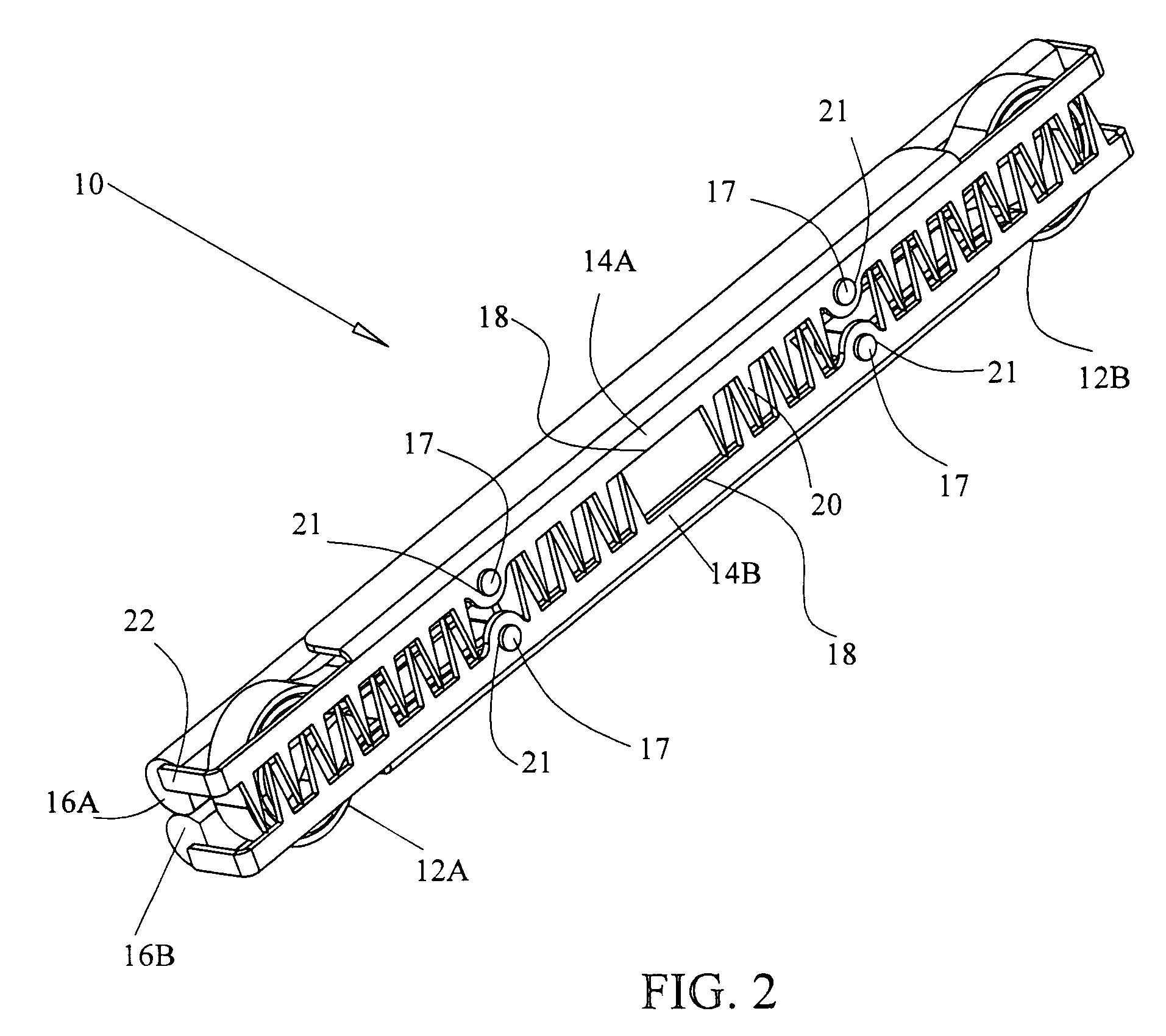
[0120]Reference is now made to FIGS. 2-3B where FIG. 2 presents a view of a non-unitary compression clip constructed according to the present invention. In FIG. 2 the clip is shown in its closed position. FIGS. 3A and 3B present a view of the compression clip shown in FIG. 2 in its open position.

[0121]Clip 10 is constructed of two shape memory hinge springs 12A and 12B, also herein often denoted as force appliers. Typically, but without intending to be limiting, the shape memory material is a Ni—Ti alloy. The operation of the clip relies on shape memory effects exhibited by these materials. Springs 12A and 12B may be made of a single wire or flattened wire or strip or it may be constructed of two or more wires, flattened wires or strips connected together at their ends. Furthermore, in some embodiments, the springs may be constructed to have a coiled shape.

[0122]Clip 10 further includes two securing elements 14A and 14B, each of which has a series of teeth 20 for grasping tissue. Ea...

second embodiment

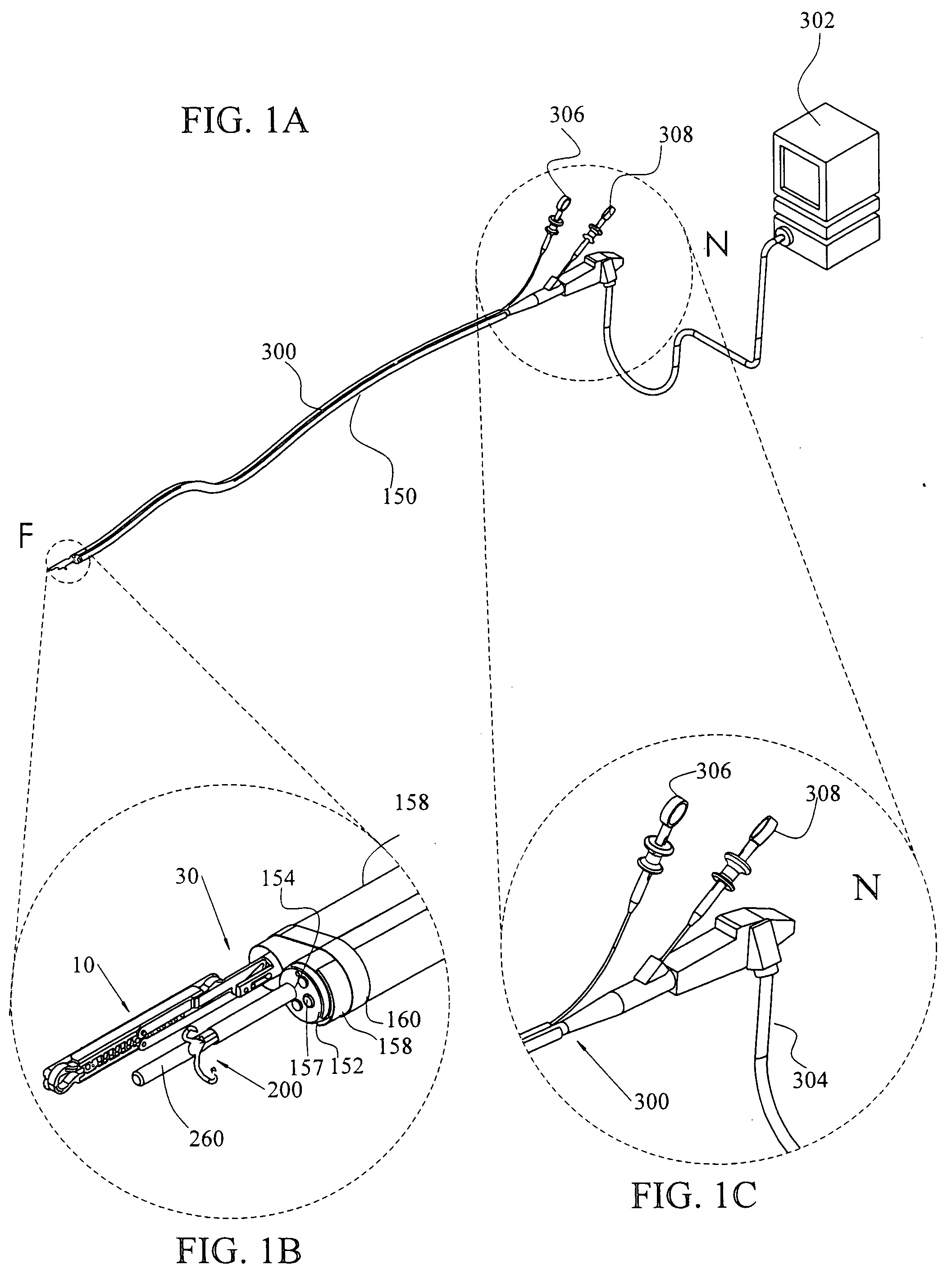
[0147]FIGS. 10-13, to which reference is now made, show various views of a clip applier constructed according to the present invention. The applier is intended for use with the surgical compression clip (slightly modified as discussed below) shown in and discussed in conjunction with FIGS. 2-3B. FIG. 10 shows the clip applier in its closed position, while FIG. 11 shows the applier in its open position.

[0148]Turning to FIG. 11 first, clip applier 50 includes insertion links 60A and 60B which are swing jointed by links 62A, 62B, 64A, 64B and central bar 66. An operating cable (not shown) is connected to the proximal end of central bar 66 and inserted into spring 52. The latter connection can be achieved by welding or any other connecting method or means known to those skilled in the art.

[0149]Insertion links 60A and 60B each have extensions (not shown) which are positioned on their distal end so that these extensions are insertable into cylindrical elements 58A and 58B. As shown in FI...

third embodiment

[0168]a compression clip constructed according to the present invention is shown in FIGS. 24A and 24B, to which reference is now made.

[0169]From FIG. 24A, which shows an exploded view of clip 610, it is readily apparent that many of the elements presented there have been encountered and described previously in conjunction with previously discussed embodiments of compression clips constructed according to the present invention. Accordingly, elements that are structurally and operationally similar to previously described elements will not be described again here. Essentially identical or equivalent elements to those found in clips 10 and 510 have been numbered as in clips 10 and 510 with the prefix 600.

[0170]Securing and compressing elements 614A, 614B and 616A, 616B, respectively, are essentially the same as in clip 510. Hinge springs 612A and 612B are unsymmetrical as in clip 510. Again, there is a bi-directional connector 617 on the shorter legs 609A and 609B of hinge springs 612A ...


PUM


Abstract

A surgical clip assembly which includes a pair of generally linear compression elements for securing tissue between them and for applying to the secured tissue a compression force. The clip assembly has an initial, open position in which the linear compression elements may be positioned about tissue to be secured between them. The assembly also has a final, closed position where the compression elements are substantially parallel to each other, applying a compressive force to the secured tissue. The clip assembly also includes a force means disposed between the pair of compression elements and operative to transmit operational forces between them.

Description

CROSS REFERENCE TO RELATED APPLICATION[0001]This application claims the benefit of U.S. Provisional Application No. 60 / 780,446, filed Mar. 9, 2006.FIELD OF THE INVENTION[0002]The present invention relates to the field of surgical compression clips generally, and, in particular, to the field of surgical compression clips, at least partially formed from shape memory material.BACKGROUND OF THE INVENTION[0003]Several methods are known in the art for joining tissue portions at the site of organ resections, particularly gastrointestinal (GI) tract resections, or at the site of other types of tissue perforations or tissue openings. These include threads for manual suturing, staplers for mechanical suturing, tissue adhesives and compression rings and clips.[0004]While manual suturing is universally known and relatively inexpensive, the degree of success depends considerably on the skill of the surgeon. Another disadvantage of this technique is that post-operative complications are common. F...

Claims


Application Information

Patent Timeline
Patent Type & Authority Applications(United States)
IPC IPC(8): A61B17/08
CPCA61B1/0014A61B17/0643A61B17/068A61B17/12A61B17/122A61B2017/308A61B17/1285A61B2017/00867A61B2017/00871A61B2017/0641A61B17/1227
Inventor MONASSEVITCH, LEONIDSHENHAV, BOAZHARARI, BOAZPERLE, AMIRARAD, MICHAELMILLIS, SHAHARGREENBERG, KOBBYGELLER, ALEXSZOLD, AMIRLELCUK, SHLOMOKOPELMAN, DORONBAPAYE, AMOLROSNER, DROR
Owner NITI SURGICAL SOLUTIONS
Why Eureka
Try Eureka