Method for observation of microstructural surface features in heterogeneous materials

a microstructure and surface feature technology, applied in the direction of mechanical measurement arrangement, mechanical roughness/irregularity measurement, instruments, etc., can solve the problems of inability to see with a conventional optical microscope, small surface topography, and inability to be very detailed, so as to improve the speed

Active Publication Date: 2006-09-19
BRUKER NANO INC
View PDF18 Cites 30 Cited by
  • Summary
  • Abstract
  • Description
  • Claims
  • Application Information

AI Technical Summary

Benefits of technology

[0021]We have developed a new method for exposing and imaging the near surface submicroscopic structure of materials having small heterogeneous features. This method substantially improves the speed with which the image is formed compared with the traditional metallurgical approaches using an optical microscope, scanning electron microscope, transmission electron microscope or AFM.
[0022]For many applications, this new method creates an image that reveals features that are unavailable with other methods and processes. The new method requires less equipment and less time and procedures to form the image and to create the image of the microstructural features of a test surface.
[0026]Then the precision positioner scans the selected machining tool tip across the test surface using a scanning force substantially smaller than the scribing force, perhaps smaller by as much as one to two orders of magnitude. This force must be adequate to hold the tool tip against the test surface at all times. Again, the transducer is used with closed loop control to maintain constant Z-axis force. The tool tip is scanned along closely spaced linear paths. The tool tip distance from the Z-axis datum plane is sampled at a frequency that allows for creating a relief map of the test surface's topographical features.
[0030]Then using the same tool to scan across the material surface with a substantially reduced force readily and conveniently provides much useful structural information about the overall material properties. That is, the combination of relatively high, constant force machining and low, constant force scanning offers a new method of observing microstructural features without altering the crystal lattice, grain or other submicron molecular structures in the test surface. The ability to use the same system with the same tool for both machining and scanning substantially reduces the testing time and equipment requirement.

Problems solved by technology

This surface topography may be very small and detailed, and quite impossible to see with a conventional optical microscope.

Method used


Image

  • Method for observation of microstructural surface features in heterogeneous materials
  • Method for observation of microstructural surface features in heterogeneous materials
  • Method for observation of microstructural surface features in heterogeneous materials

Examples


Embodiment Construction

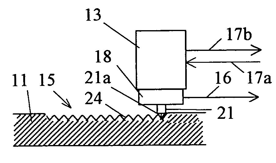
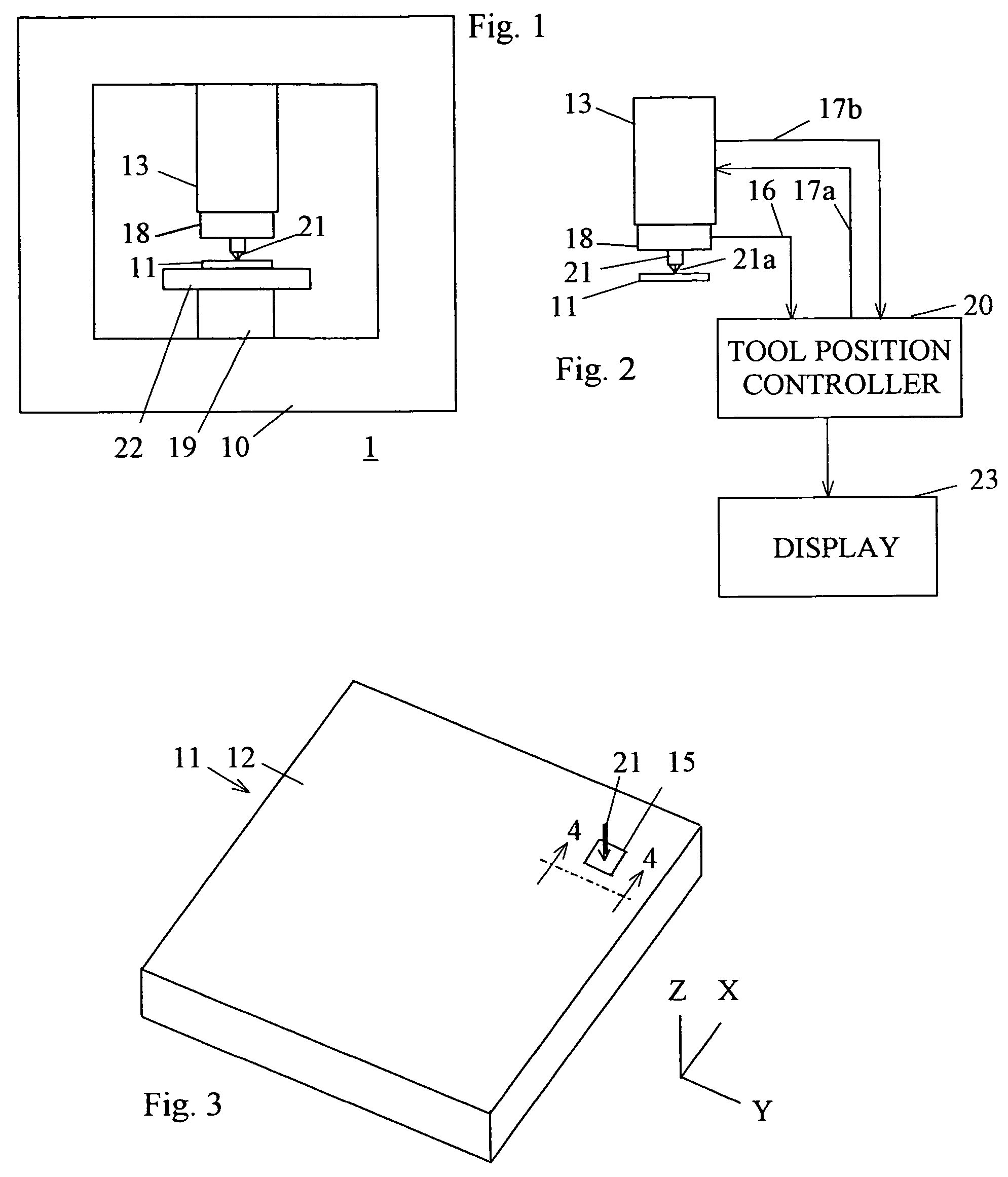
[0039]The method of the invention forms an image of variations in microstructural properties reflected as hardness or wear resistance at the nanometer level for a material sample 11 such as shown in FIG. 3. Sample 11 may comprises any of a wide variety of metals, ceramics, biological materials, plastics, coatings, or amorphous materials with heterogeneous small features. Of course, parameters used in implementing the method of the invention depend on the type of material comprising sample 11.

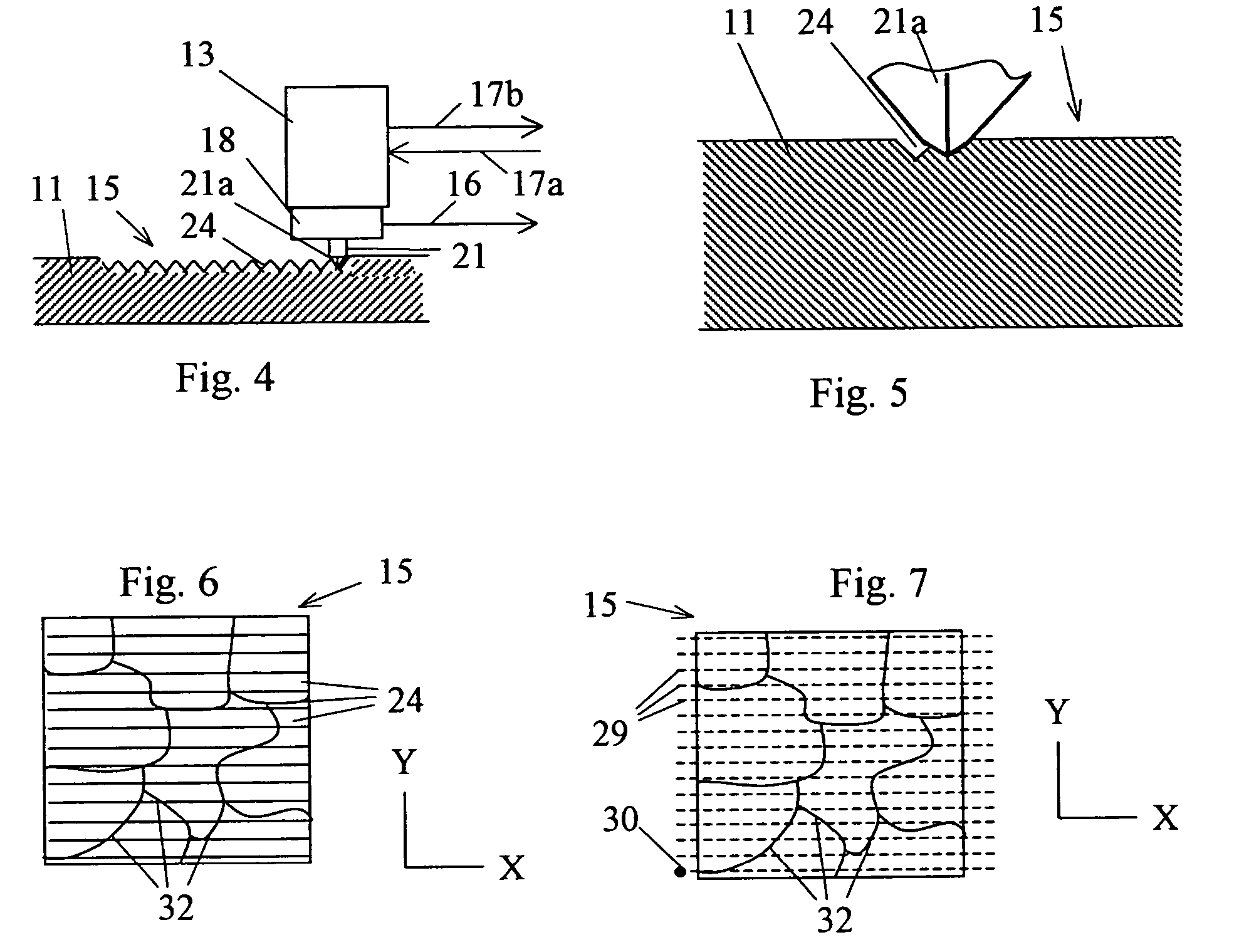
[0040]Sample 11 has a test surface 12 in which a sample area 15 is selected. Sample area 15 may be approximately square with a side whose length is in the approximate range of 50 nm to 80 microns (μm), with 10 μm a typical length.

[0041]Tool 21 is shown positioned within sample area 15. Precision positioner 13 carries tool 21 as previously described. Tool 21 will normally be approximately positioned within area 15 by movement of stage 22. Stage 22 may be shifted either under manual control, or by...


PUM


Abstract

A method for forming a topographical image of the heterogeneous variations in a surface of a material has a first machining step and a second scanning step. The preferred machining step uses a preselected scribing tool to scribe a plurality of adjacent grooves in a selected material surface at a preselected constant force. This machining step produces a machined surface whose local elevations relative to a datum plane are dependent on the local hardness or wear resistance of the surface. Then the scanning step shifts the scribing tool across the surface in contact with the surface, and measures the elevation of the tool at a plurality of selected surface coordinates. The measured elevations allow formation of a topological map depicting sub-micron structural features of the surface.

Description

BACKGROUND OF THE INVENTION[0001]Many types of devices for proper functioning depend on specialized characteristics of the materials from which the devices are made. Steel must be strong enough and hard enough to serve as a good drill bit material. A bearing material must be made of a material that is adequately hard and yet machinable to adequate smoothness. Electrical wire must have adequate conductive and ductility characteristics. The list is endless.[0002]One particular set of characteristics that is often important in testing materials is the submicroscopic, or nanometer structure. In particular, designs of various types of devices depend on the submicroscopic surface structure of materials from which the devices are made. One example is in computer hard drives, where these characteristics of both the individual disks and the heads that read and write the data affect the allowable bit density and the bearing characteristics of the head and disk surfaces.[0003]A number of devic...

Claims


Application Information

Patent Timeline
Patent Type & Authority Patents(United States)
IPC IPC(8): B43L13/00G01B5/20G01B5/28
CPCB82Y35/00G01Q60/366G01Q30/04
Inventor YANG, DEHUAWYROBEK, THOMAS J.
Owner BRUKER NANO INC
Why Eureka
Try Eureka