Impact tool and method of controlling impact tool

Active Publication Date: 2015-11-26
HITACHI KOKI CO LTD
View PDF11 Cites 385 Cited by
  • Summary
  • Abstract
  • Description
  • Claims
  • Application Information

AI Technical Summary

Benefits of technology

[0007]By the way, recently, increase of the output of the impact tool has been achieved and therefore it is possible to obtain a high rotational speed and a high fastening torque while reducing the size of the tool. However, realizing the high fastening torque causes striking stronger than necessary to be applied when performing the first striking in a screw fastening work

Problems solved by technology

As a result, damage risk of screw becomes even higher.
However, in this case, the time required f

Method used


Image

  • Impact tool and method of controlling impact tool
  • Impact tool and method of controlling impact tool
  • Impact tool and method of controlling impact tool

Examples


first embodiment

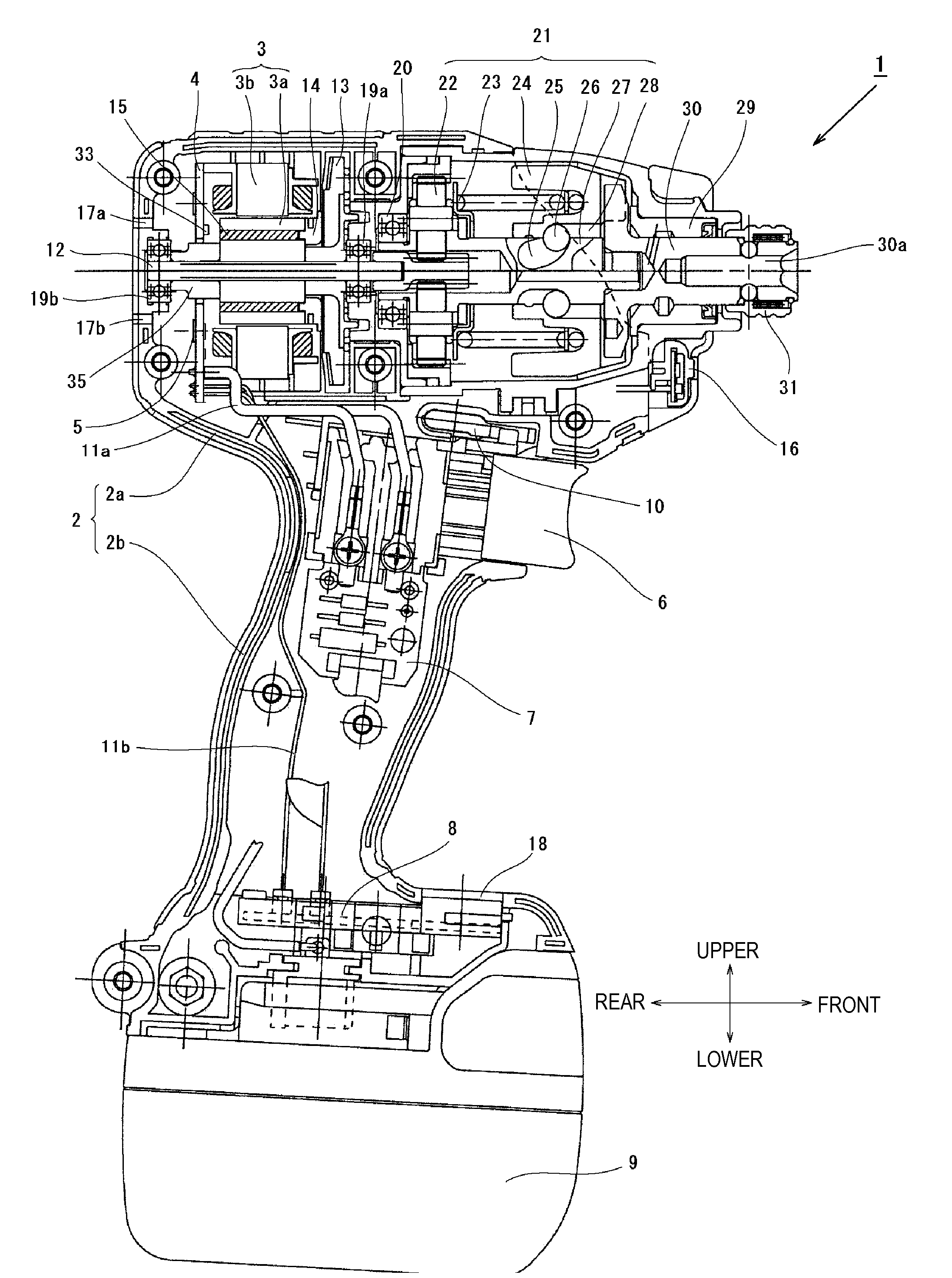
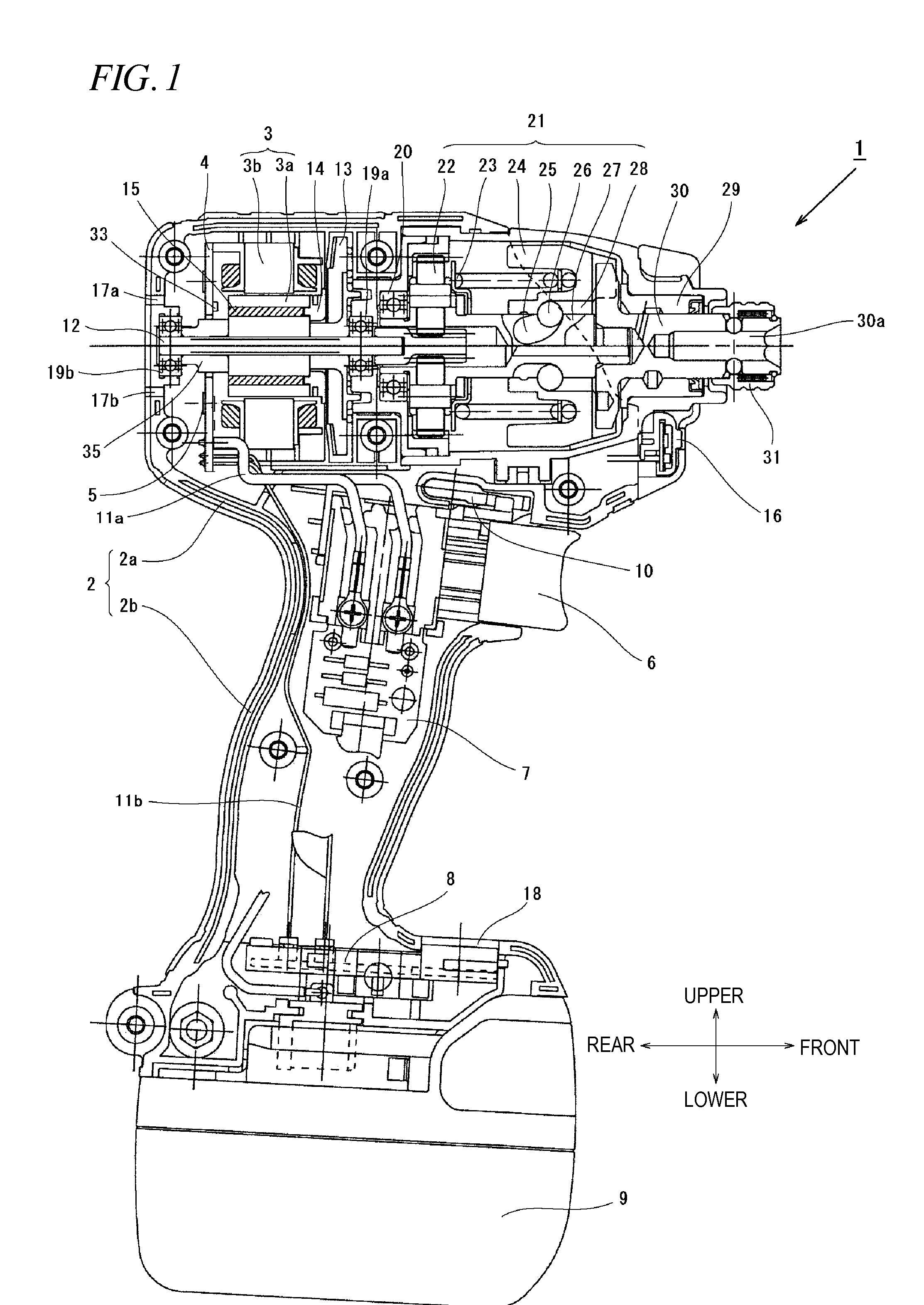
[0055]Hereinafter, an illustrative embodiment of the present invention will be described with reference to the accompanying drawings. In the following description, a front-rear direction and an upper-lower direction are referred to the directions indicated by arrows of FIG. 1.

[0056]FIG. 1 is a view showing an internal structure of an impact tool 1 according to the present invention. The impact tool 1 is powered by a rechargeable battery 9 and uses a motor 3 as a driving source to drive a rotary striking mechanism 21. The impact tool 1 applies a rotating force and a striking force to an anvil 30 which is an output shaft. The impact tool 1 intermittently transmits a rotational striking force to a tip tool (not shown) such as a driver bit to fasten a screw or a bolt. Here, the tip tool is held on an mounting hole 30a of a sleeve 31. The brushless DC type motor 3 is accommodated in a cylindrical main body 2a of a housing 2 which is substantially T-shaped, as seen from the side. A rotati...

second embodiment

[0076]Next, a second embodiment of the present invention will be described with reference to FIG. 7 to FIG. 9. Similarly to the first embodiment, the second embodiment has a configuration that the high duty ratio is lowered just before the first striking is performed. However, in the second embodiment, control is made in such a way that the duty value is gradually increased at a predetermined rate after the duty ratio is lowered to a low duty ratio and while the motor current is maintained in a state of being equal to or less than the current threshold I1.

[0077]Now, relationship among the motor current, the duty ratio of PWM drive signal and the fastening torque in the impact tool of the second embodiment will be described by referring to FIG. 7. In each graph of (1) to (3) of FIG. 7, a horizontal axis represents time (in milliseconds) and each horizontal axis is commonly represented. The present embodiment illustrates an example where a short screw is fastened using the impact tool...

third embodiment

[0082]Next, a third embodiment of the present invention will be described with reference to FIG. 10 and FIG. 11. In the third embodiment, a control for returning the duty ratio from the low duty ratio to the high duty ratio is added to the first embodiment. FIG. 10 shows relationship among the motor current, the duty ratio of PWM drive signal and the fastening torque in the impact tool of fastening a long screw. First, when rotation of the motor 3 is started at time t0, a motor current 131 is abruptly increased as in an arrow 131a in accordance with the fastening situation of the screw and exceeds the current threshold I1 at time t1. Therefore, the operation unit 40 decreases the PWM duty ratio from 100% to 40%. However, thereafter, the motor current 131 reaches a peak as in an arrow 131c and then is rapidly decreased as in an arrow 131d whereby the motor current is often less than a return current threshold (third threshold) IR. This is a phenomenon that the motor current value I i...


PUM


Abstract

An impact tool includes: a motor; a trigger; a controller configured to control driving power supplied to the motor using a semiconductor switching element according to an operation of the trigger; a striking mechanism configured to drive a tip tool continuously or intermittently by rotation force of the motor, the striking mechanism including a hammer and an anvil. The controller drives the semiconductor switching element at a high duty ratio when the trigger is manipulated. The motor is driven so that the duty ratio is lowered before a first striking of the hammer on the anvil is performed and the first striking is performed at a low duty ratio lower than the high duty ratio.

Description

TECHNICAL FIELD[0001]The present invention relates to an impact tool and, more particularly, to an impact tool in which a control method of a motor used as a driving source is improved.BACKGROUND ART[0002]A portable impact tool, especially, a cordless impact tool which is driven by the electric energy accumulated in a battery is widely used. In the impact tool where a tip tool such as a drill or a driver is rotationally driven by a motor to perform a required work, the battery is used to drive a brushless DC motor, as disclosed in JP2008-278633A, for example. The brushless DC motor refers to a DC motor which has no brush (brush for rectification). The brushless DC motor employs a coil (winding) at a stator side and a permanent magnet at a rotor side and has a configuration that power driven by an inverter is sequentially energized to a predetermined coil to rotate the rotor. The brushless DC motor has a high efficiency, as compared to a motor with a brush and is capable of obtaining...

Claims


Application Information

Patent Timeline
IPC IPC(8): B25B23/147B25B21/02
CPCB25B21/026B25B23/1475B25B21/02
Inventor IWATA, KAZUTAKAKOMURO, YOSHIHIRO
Owner HITACHI KOKI CO LTD
Why Eureka
Try Eureka