Modular Rolling Mill

Active Publication Date: 2012-11-15
PRIMETALS TECH USA
View PDF1 Cites 0 Cited by
  • Summary
  • Abstract
  • Description
  • Claims
  • Application Information

AI Technical Summary

Benefits of technology

[0015]When viewed in the direction of rolling, the first and second shafts of the respective first and second gear units are advantageously driven at progressively higher rotational speeds, and the input shafts of the rolling units are connected to the respective pairs of rolls shafts by gears sized to effect a percentage spe

Problems solved by technology

This design is unique to the modular mill concept, and is not readily adaptable for use at other mill loca

Method used


Image

  • Modular Rolling Mill
  • Modular Rolling Mill
  • Modular Rolling Mill

Examples


Embodiment Construction

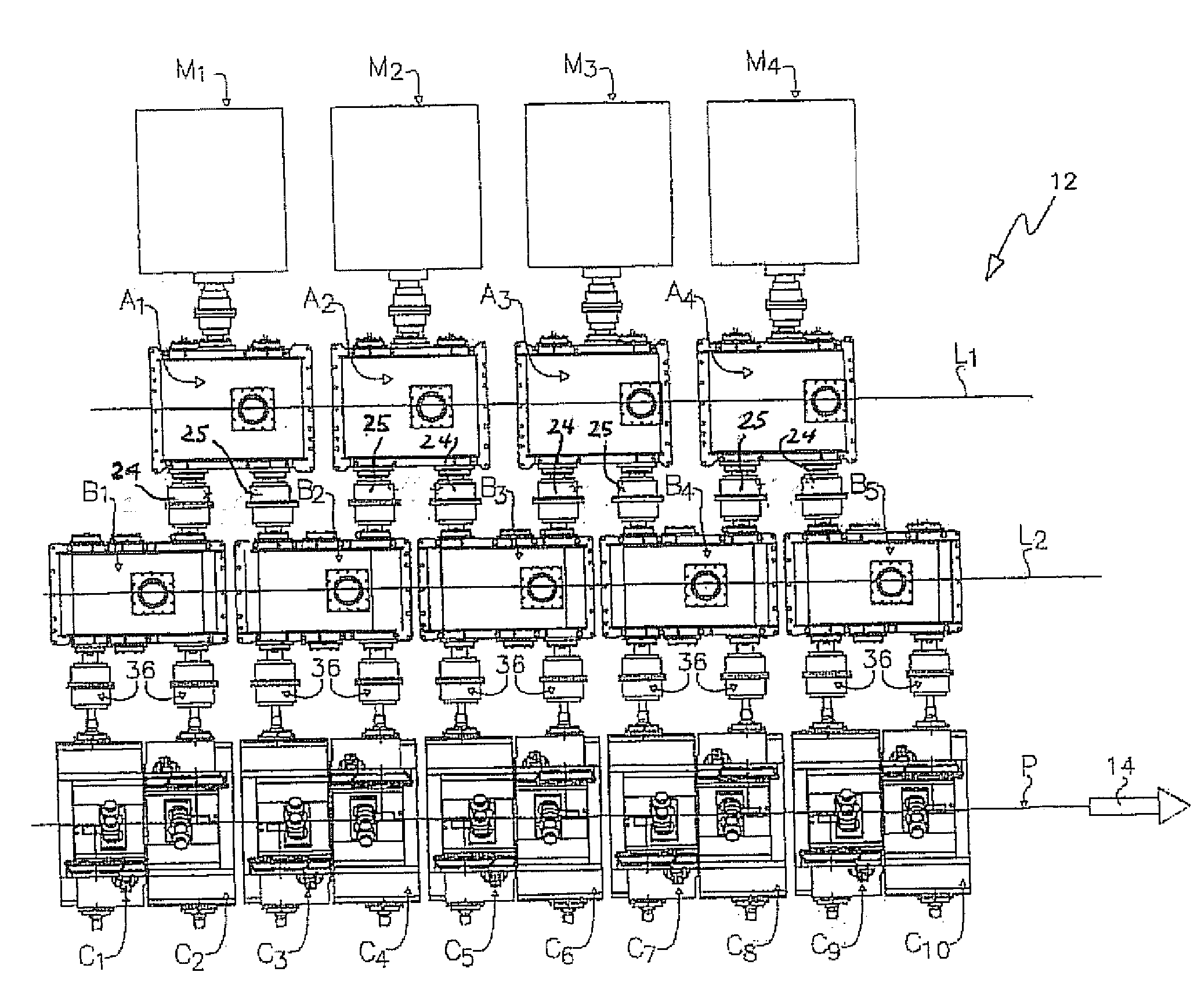
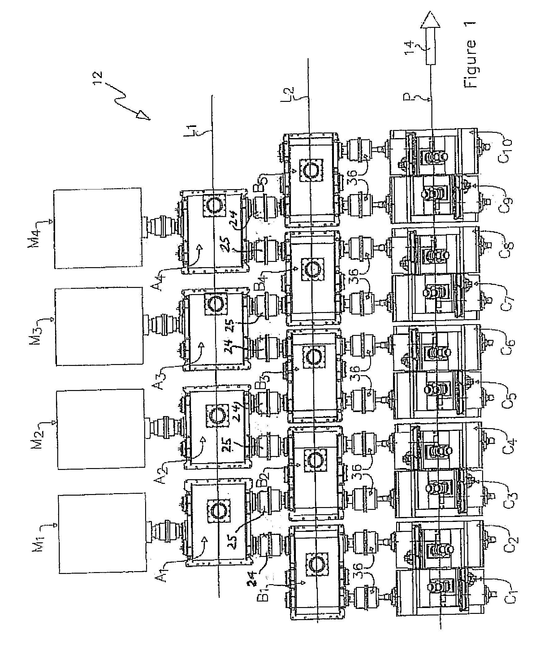
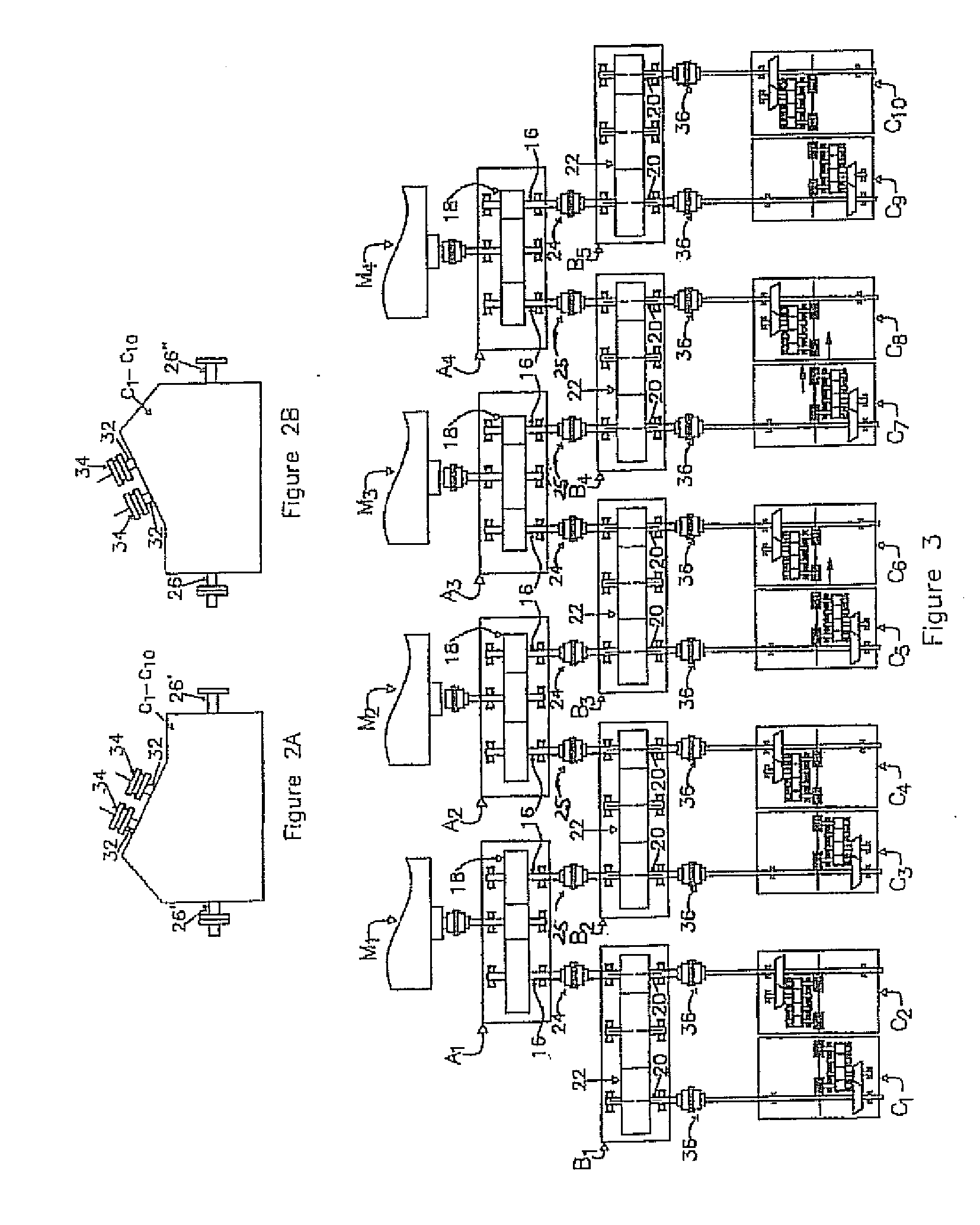
[0025]With reference initially to FIGS. 1 and 3, a modular rolling mill in accordance with the present invention is shown at 12. The rolling mill 12 is designed to roll long products such as bars, rods and the like along a mill pass tine “P” in a rolling direction indicated diagrammatically by arrow 14. The mill includes first gear units A1-A4 arranged along a first line L1 parallel to the mill pass line P. The first gear units are driven respectively by motors M1-M4 mechanically connected to pairs of first shafts 16 by internal gear sets 18.

[0026]Second gear units B1-B5 are arranged along a second line L2 between and parallel to both the first line L1 and the mill pass line P. Each second gear unit has a pair of second shafts 20 mechanically interconnected by a gear set 22. When viewed in the rolling direction, the second gear units B1-B5 are offset with respect to the first gear units A1-A4. First couplings 24 and 25 serve to connect the first shafts 16 of each first gear unit A1-...


PUM

PropertyMeasurementUnit
Speedaaaaaaaaaa

Abstract

A modular rolling mill has a mill pass line along which products roll. The rolling mill comprises first gear units arranged along a first line parallel to the mill pass line. Each first gear unit is driven individually by a motor and has a pair of mechanically interconnected first shafts. Second gear units are arranged along a second line between and parallel to the first line and the mill pass line. Each second gear unit has a pair of mechanically interconnected second shafts. Rolling units are arranged along the mill pass line, which are driven by an input shaft and has a pair of roll shafts carrying work rolls. First couplings connect the first shafts of each first gear unit to second shafts of two successive gear units, and second couplings releasable connect the second shafts of the second gear units to the input shafts of two successive rolling units.

Description

CROSS REFERENCE TO RELATED APPLICATIONS[0001]This application is a continuation in part of U.S. application Ser. No. 12 / 797,656 filed on Jun. 6, 2010, the entire contents and substance of which is hereby incorporated by reference herein.BACKGROUND[0002]1. Field of the Invention[0003]This invention relates generally to rolling mills, and is concerned in particular with the provision of an improved modular finishing mill for rolling long products such as rods, bars and the like.[0004]2. Description of Related Art[0005]With reference to FIG. 5A, a known modular finishing mill of the type described in U.S. Pat. No. 5,595,083 to Shore comprises a plurality of rolling units R1-R5 arranged sequentially on a mill pass line P along which products are rolled in a rolling direction indicated by arrow 10. Gear units A1-A4 are arranged along line L parallel to the mill pass line. The gear units are driven individually by motors M1-M4 and are offset with respect to the rolling units in the rollin...

Claims


Application Information

Patent Timeline
IPC IPC(8): B21B31/08B21B13/12
CPCB21B35/02B21B1/18
Inventor SHORE, T. MICHAELSHORE, S. MARK
Owner PRIMETALS TECH USA
Why Eureka
Try Eureka